Day 6 - Section 1 - Sensing the light
| Site: | ΕΛ/ΛΑΚ Moodle |
| Course: | Robotics - 3D Printing - Internet of Things |
| Book: | Day 6 - Section 1 - Sensing the light |
| Printed by: | Guest user |
| Date: | Tuesday, 23 June 2026, 1:33 PM |
Description
After the completion of this section the students will be able to:
- describe and use a photoresistor
- build a circuit to sense and measure the light
- use the Serial Monitor inside the Arduino IDE
- visualize the light amount to values into the Serial Monitor
More or less light....
In this lesson, we 'll learn how we can measure the amount of light with the help an electronic device that is called 'photoresistor'.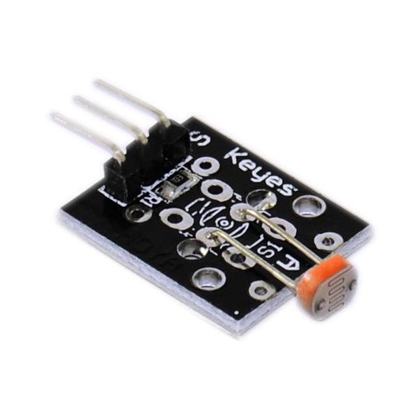
So, how can we find the exact amount of light that passes through the device at any time using NodeMCU and Arduino IDE? The answer is "we can not do it using only these", but we can build a circuit that will help us watch the changes that the light causes, passing through the photoresistor. For the purposes of this experiment we have to build the following circuit.

Use the Serial monitor to watch the light effects
Before explaining how the Serial monitor works, let's have a look on the code that we have to upload to the NodeMCU, in order to measure the light. Study, copy and then paste it into the Arduino IDE:
void setup()
{
    Serial.begin(9600);  //Begin serial communcation
}

void loop()
{
   Serial.println(analogRead(A0)); //Write the value of the photoresistor to the serial monitor.

   delay(10); //short delay for faster response to light.
}
A few words about the program:
First, in the setup() section, we initialize the communication speed between the computer and the NodeMCU (Serial.begin(9600);).
In the loop() section, we read the analogue value of pin A0 (analogRead(A0);) and then we display it into the Serial Monitor in a new line (Serial.println();). Notice here that there is another command (Serial.print();) which prints the output without opening a new line. But, here we use Serial.println(); command.
The last command delay(10); is telling the NodeMCU to wait for a little time (10ms) before continuing.
In order to open the serial monitor in Arduino IDE and watch the values we need to press the icon with the magnifying glass:

Then you will see a picture like this, that will be refreshing fast:

Try now to throw some light on the photoresistor (maybe with a flashlight or using your mobile phone) and watch the values changing. The limits are 0-1023 so any value between these limits represents an amount of light at any given moment.
