3D modeling for real electronics
| Site: | ΕΛ/ΛΑΚ Moodle |
| Course: | 3D printing with circuits and Arduino |
| Book: | 3D modeling for real electronics |
| Printed by: | Guest user |
| Date: | Tuesday, 9 June 2026, 7:21 PM |
Description
Build your first interactive 3D prints.
1. The cutouts of the circuit assemblies
On Tinkercad, you might noticed how for each circuit assembly, there is a corresponding Cutout. The cutout makes a space inside your design where the printed holder will reside. It provides the perfect size of hole needed achieve a good press fit when the Glow or Move holder is placed into your printed object.
In this module we will do a walk-through for incorporating the Move circuit assembly into a unique design.
2. Adding the Move cutout
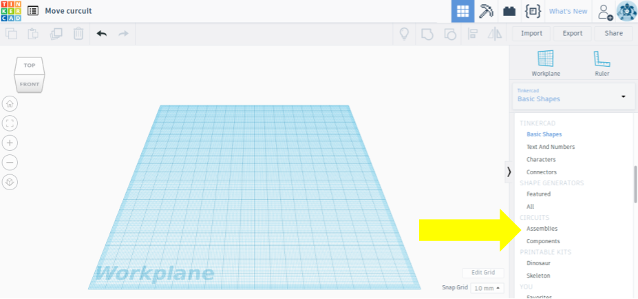
First, sign in on Tinkercad and create a new design. You can find the Circuit Assemblies under the Basic Shapes menu on the right.
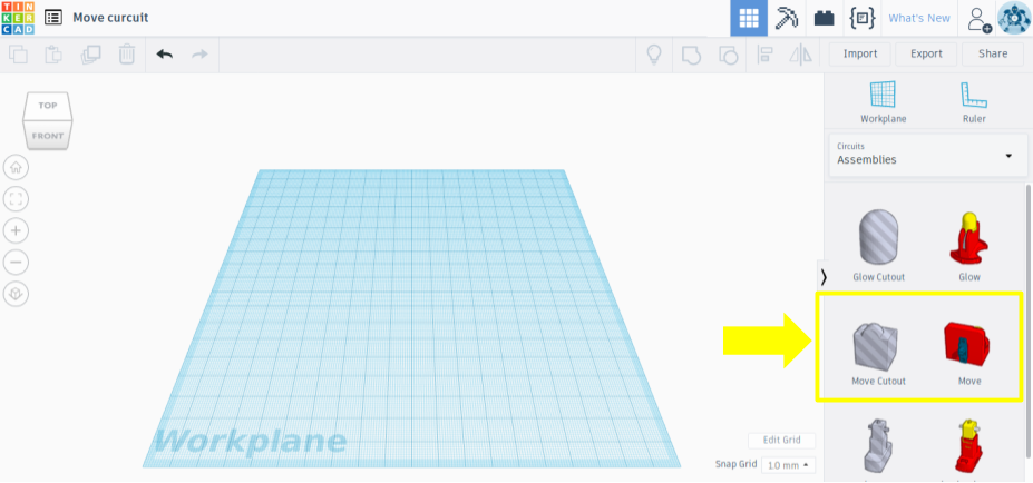
Click on Assemblies and you can see the Glow and Move holder parts we worked on in the last modules, as well as their corresponding cutouts as "holes". Drag and drop the Move Cutout onto the workplane.
3. The cutout design
If you also add the Move holder on the correct position, you can see from different angles how it fits exactly inside the hole.

The Cutout is designed in such a way that the hole includes the switch and leaves enough space in the bottom of your design for it.
However, if you'd prefer that the switch sticks out past the wall of your design, it is doable by keeping that extra amount of the Cutout sticking out the side of the wall before grouping the parts.
4. Importing a suitable shape
In this tutorial, we are going to use the first option, of incorporating the assembly into the bottom of a shape. For this, the bottom surface of this shape needs to be originally flat.
We are going to use this design of a fox, found on Thingiverse. You can fetch the .stl file from here.
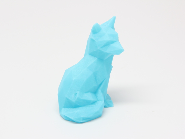
However, if you are feeling adventurous, you can use any other shape with a flat bottom from the Shapes menu or import another design of your choice.
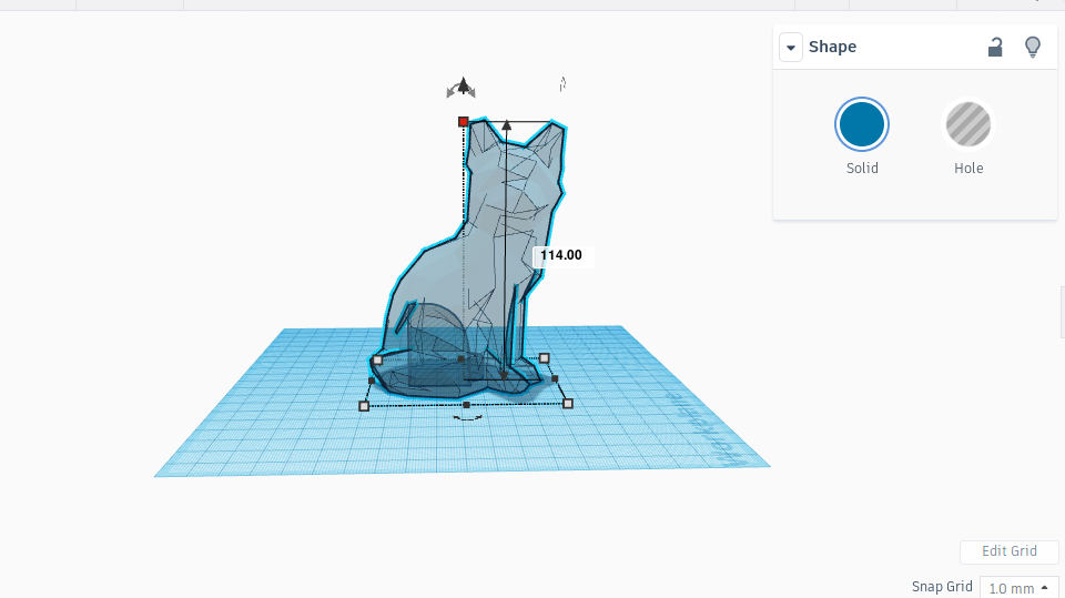
In order to be able to move and resize the fox design to fit the Cutout, we are going to make it transparent from the Shape window that pops up when selecting a shape of the workplane.

5. Incorporating the cutout
As we chose to have the switch at the bottom of the design, we need to rotate the Cutout 90 degrees using the rotate arrows.
We then move the Cutout, so that it is completely inside the fox.


We need to check the bottom and side views to confirm that the Cutout is in the right position, and that it is not sticking out of any of the shape walls.
We also need to leave enough space for an adequate amount of printing
material between the Cutout and the outside of the shape (at least 3mm).
We will slightly enlarge the fox, just to be on the safe side.

We then make the fox shape a visible solid again by unchecking the Transparent box. Triple check from all angles that the Cutout is placed correctly!
In order to select both shapes, we click and drag the cursor over the fox shape and the Cutout within it or hit Ctrl+A. Click on the Group icon in the upper right corner to remove the cutout shape from the main shape.

There should now be a hole in the design in the shape of the Cutout.