Meet the circuit
| Site: | ΕΛ/ΛΑΚ Moodle |
| Course: | 3D printing with circuits and Arduino |
| Book: | Meet the circuit |
| Printed by: | Guest user |
| Date: | Tuesday, 21 July 2026, 8:31 AM |
Description
The foundation of all electronics projects.
1. What is a circuit?
An electrical circuit is a network of electrical components connected together with wires -or other lines that allow electricity flow- in a closed loop.
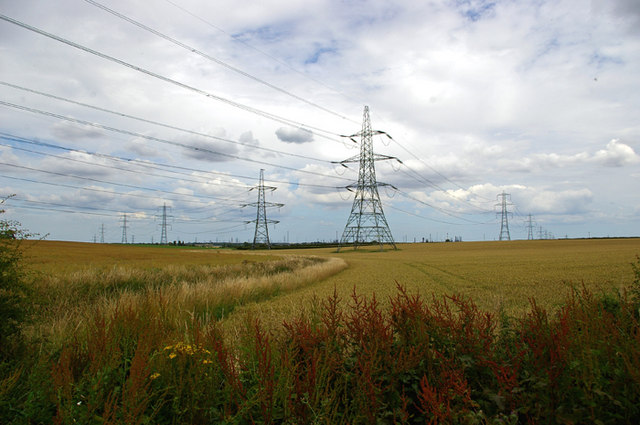
This is a circuit:
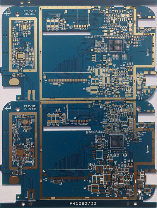
This is also a circuit:
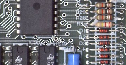
And this is also a circuit:

2. Circuit parts
In order to create a circuit we need two main things: conductive elements and electrical components.
A circuit is defined by its components, but without connections between them there is no closed loop, hence no electricity flow, hence no circuit. In order to make these connections, we mostly use metallic elements, such as wires or lines that are electrical conductors, which means they allow electricity flow.
In electronic devices and computers these lines are usually printed on a flat surface.
The parts, such as resistors, power sources and LEDs, listed in the first page are some of the most common electrical components. We are going to learn more about them as we are testing them in real circuits.
3. Schematics and symbols
The first circuit we are to build in this module will be a “more advanced” version of the Glow circuit we assembled in 3D printing with circuits.
This is a drawing of the circuit that we will build:
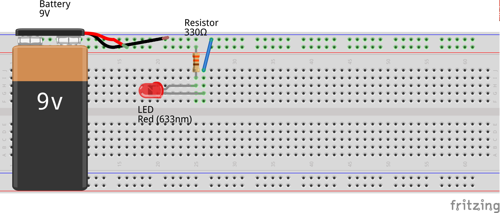
We will use an LED, a resistor, a jumper wire and a 9V battery with its cap and connectors.
It is a fairly simple circuit, easy to understand from a drawing. However, as we add more components and complexity to circuits, it will be harder to illustrate all connections and functions. This is why in electronics we use schematics.
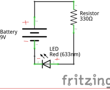
A schematic is a diagram of the relationships of the electronic components in a circuit. In a schematic, you see the circuit components and how they are connected. This is the schematic of the circuit we are going to build: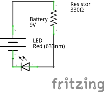
All common components have a symbol that is used to represent them in schematics. You can find more about them here and we will present each component's symbol as we go through the course.
4. This circuit: LEDs
We are making a basic circuit of one LED, a resistor and a battery.
LEDs
One important thing to remember about LEDs is that they have a polarity, or direction in which they must be placed in order to work in a circuit. If we place the LEDs backward, they won’t light up. How do we know the orientation of an LED?
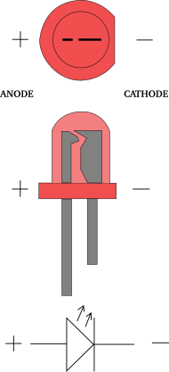
LEDs have two legs, or leads, which are different lengths. The longer lead is known as the anode, the side of the LED that we will connect to power. The shorter leg is called the cathode, which will be pointed away from our power source. If you place the LED in backward, it won’t light up but it also will not damage anything in your circuit.
However, as a maker, you should not blindly trust leg size, as somebody might have previously clipped the legs!
5. Using the breadboard
Now that we know which connections to make and how between parts, how do we build the circuit?
When there is a need to quickly and temporarily prototype a circuit, we will be using a breadboard.
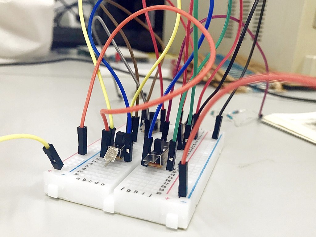
Breadboards
are meant to make quick non-permanent connections between electronic
components. They are covered in tiny socket holes which are connected in
rows. The board itself is broken into four sections. There are two
inner sections full of short horizontal rows/bars, and two outer sections
with longer vertical rows/rails.
The inner sections are typically used
for connecting components, and the outer sections are typically used as
power bus lines. In other words, you can connect a battery to one of the
outer lines and then power components on the inner section by
connecting a wire to this section.
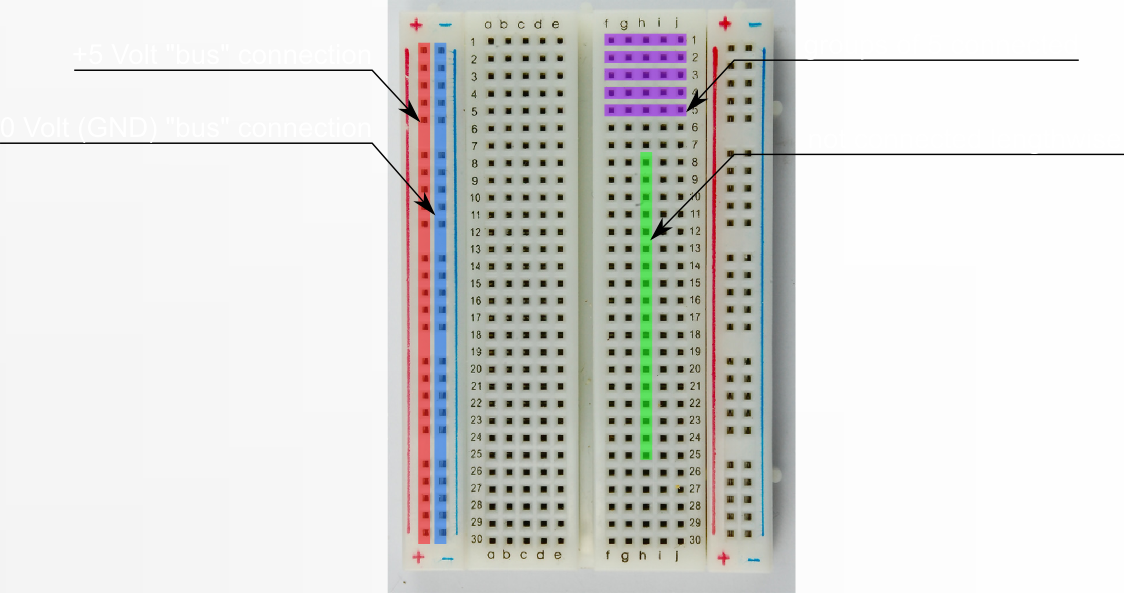
These are marked in red and blue and are meant to signify a row for power (red) and a row for ground (blue). Not all breadboards are marked with lines like this, but they are all laid out the same way.
To use a breadboard to prototype circuits, you simply insert components
or wire into the appropriate sockets to connect them together.
6. Build the circuit
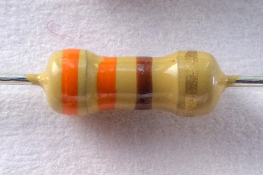
Pick the resistor
Add the LED
The anode (long lead) goes in the same row of tie points as the resistor. The cathode (short lead) goes into the next row.
Next we add a jumper wire to connect the LED cathode to the ground bus (-) of the breadboard.
Connect the power source
