Powering a circuit: electricity
| Site: | ΕΛ/ΛΑΚ Moodle |
| Course: | 3D printing with circuits and Arduino |
| Book: | Powering a circuit: electricity |
| Printed by: | Guest user |
| Date: | Sunday, 28 June 2026, 11:19 PM |
Description
Tame electrical waves and currents.
1. Power vs. ground
As we mentioned before, the battery has a positive and a negative end. The convention has it that the positive side produces power (+) and the negative one is ground (-).

2. Debugging
In the technology world, and especially in computer systems, we use the word 'debugging' to describe the process of finding errors and fixing them.
In case your LED didn't light up, we need to debug it and figure out what went wrong.
Power properly connected?
LED properly connected?
Resistor?
- a much smaller resistor did not limit enough the flow of electricity and you burned your LED (when that happens, dispose it!)
- a much larger resistor limited too much the flow of electricity so not enough power to light up the LED
Connections
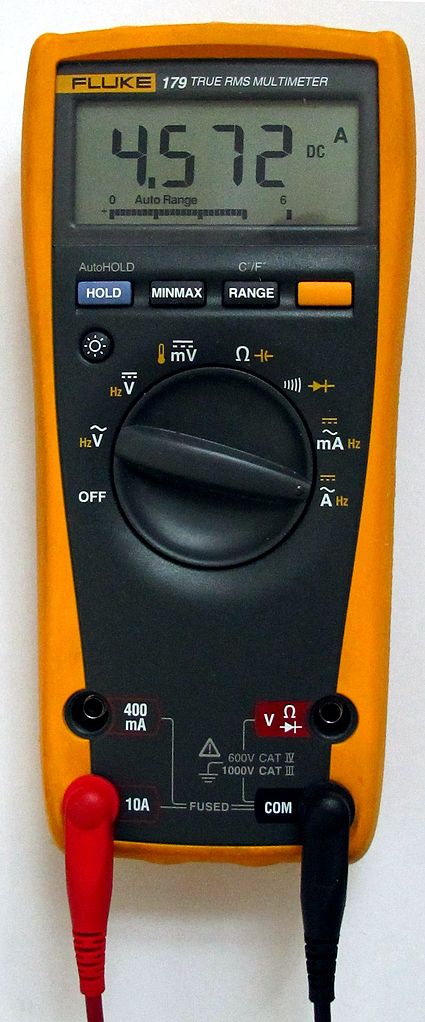
3. The multimeter
A multimeter is a tool used for a wide range of electrical
measurements.
A typical multimeter
will measure voltage (voltmeter), current (amperemeter), resistance (ohmmeter), and continuity.
To set up the multimeter, we plug the black probe into the ground / common
port and the red probe into the voltage terminal.
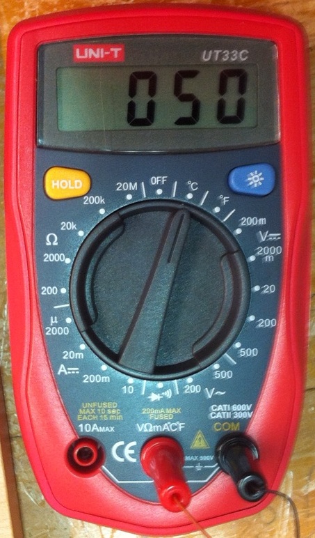
A multimeter also typically has a display that shows the measurements.
For now, we will only use the multimeter to test for continuity, so we will turn it to the beeper/continuity mode; there should be a sign similar to this one:
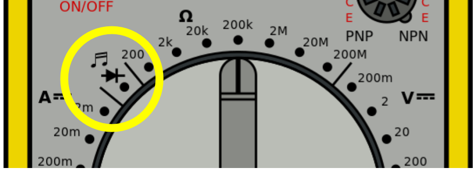
Once we are ready, first we touch one probe with the other to see if it works. You should hear a beeping sound which indicates a connection between the two points the probes are touching.
Now check the connections in your breadboard between each component to see if they are in the proper tie points.
You may learn more about using the multimeter with this video:
4. Conductors vs. insulators
As we have mentioned when explaining lines and wires, conductor materials are the ones that allow electricity flow.
Insulators on the other hand, prevent the flow of electricity through it. Typically insulators are materials like rubber, wood, and plastic.
In the Glow and Move circuits, the 3D printed parts were insulating enclosures for the circuits, which were connected through their metallic parts.
5. AC vs. DC

"Ground"

AC to DC
Safety
6. Voltage and current
We have mentioned these terms a few times already, without having them explained properly.
Imagine a ball being thrown through the air.
- Voltage is the speed the ball is travelling. This is measured in Volts. It's symbol is a capital V.
- Current is the size of the ball being thrown. This is measured in Amperes (or Amps for short). Its symbol is a capital A.
All DC electricity can be thought of as having a voltage and a current. In order to determine what these are, you can use a multimeter.
Measure the voltage of a battery
Place the red probe on the positive terminal of the battery. Place
the black probe on ground (or "minus") terminal of the battery. You
should get a reading close to its nominal value, e.g. 9V.
If you reverse the probes of the multimeter you will notice that the
meter will give you a negative voltage reading. The reason for this is
that DC electricity has a positive voltage and a ground voltage. The reading on the multimeter is actually the black probe's voltage level subtracted from the level of the red probe.
7. Ohm's law
Let's imagine the ball again. If you have a small ball travelling at a very high speed, it could potentially have as much or more power as a large ball travelling at a very low speed. In this way, you could say there is a direct relationship between the speed a ball is travelling, the size of the ball, and the potential power of the ball.

Of course though, we are actually not really talking about balls, but electricity. When dealing with electricity, voltage and current are in a direct relationship with power. In a circuit, power is expressed in terms of Watts. The symbol for this is a W.
Watts = Voltage * Current
There is also another factor we have yet to talk about that also plays a
role, and that is resistance. In our analogy, resistance is the
headwind that the ball must fight against to move forwards. On a calm
day, there might be little resistance to its flight, but on a windy day,
it might have to fight against the wind pretty hard. Again, we are
actually talking about electrical resistance in a circuit and not
throwing a ball.

Resistance pushes against the flow of electricity. As such, it is also in direct relationship with Watts, Voltage and Current. Resistance is expressed in Ohms (after it's discoverer). This mathematical relationship between Watts, Voltage, Current and Resistance is unsurprisingly called Ohm's Law.
Ohm's Law is not something you must memorize, but it will play an
important role later when determining how much resistance a circuit must
have. Thanks to this law, a circuit having a minimum amount of
resistance is not optional, but necessary. The energy in the circuit
must encounter resistance in order to expend itself. The thing in the
circuit which uses energy is considered the Load. If an electrical
supply is connected to ground without a load to use up the energy, bad
things will happen.
You should NEVER
connect your positive voltage source directly to ground.
One of the other fundamental concepts of
Ohm's Law is that electricity must encounter a minimum amount of
resistance in a circuit and be able to expend itself. If you connect
power and ground directly together, there will be a lot of energy that
has no way of expending itself. Your circuit will then try to release
this unused energy in highly antisocial ways. Basically, the energy will
turn into heat. However, having nothing in particular to warm, either
your power source or wire will start to dramatically heat up. This can
potentially result in a damaged power supply, melted wire, a fire, or
potentially an explosion.
Another name of this phenomena is a "short circuit." You likely have heard this term before.
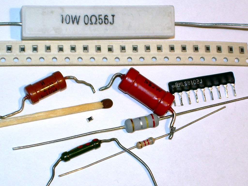
8. Resistors
A resistor is an electronic component that limits the flow of electrons. In doing so, it dissipates energy in the form of heat.

The amount of resistance that a resistor offers is measured in Ohms. The symbol for ohms is the Greek omega symbol - Ω.
In terms of electronics, the resistor reduces electrical current by a precise amount. If you consider that in a circuit you typically have a fixed input voltage, and resistors offer a fixed amount of resistance, you can then use Ohm's Law to determine how much a resistor will limit current. This is useful in a number of scenarios, including working with LEDs.
To measure ohms with a multimeter, turn the dial to the Ω symbol and selecting the proper range.
Resistor values

When reading a resistor with four stripes, the first two stripes are combined together to form a number between 1 and 99. The third marking is the multiplier. The last marking determines the tolerance.

A resistor with a gold band has a resistance with a +/- 5% tolerance or - you could say - margin of error. What this means is that the resistance can be over or under its value by 5%. So, if you had a 100K resistor and measured with a multimeter, it could read anywhere from 95K to 105K. This will be alright for the purposes of this course.
Variable Resistors
A variable resistor is a resistor whose value varies within a set range.

The simplest and most common variable resistor is the potentiometer. Every time you use a slider or knob on an electrical device, you are using a potentiometer. For instance, every single mechanical light dimmer you have ever used is a potentiometer.

Potentiometers come in a wide range of resistances, and have a physical actuator that sweeps from 0 ohms resistance to whatever value is marked upon it.
By connecting a wire to either one of its outer terminals, and another to the centre terminal, we can wire a potentiometer as a variable resistor.
We can always check which pin is which with a multimeter.