Arduino programming
| Site: | ΕΛ/ΛΑΚ Moodle |
| Course: | 3D printing with circuits and Arduino |
| Book: | Arduino programming |
| Printed by: | Guest user |
| Date: | Tuesday, 21 July 2026, 6:57 PM |
Description
Blink a LED, the Arduino 'hello world'.
1. Connecting the Arduino to the computer
First, we are going to connect the Arduino to the computer with the USB A-B cable. It looks like this:
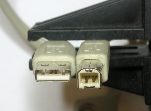
We can plug the one end to any available USB port of the computer and the other end to the USB port of the Arduino.
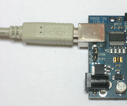
The power LED marked ON should now light up!
2. The Arduino IDE
The Arduino IDE is a free (and open source!) application for writing code and uploading it to an Arduino board. In case your computer does not already have it installed, you can find it in this download page and click the option that best describes your system, following the instructions.
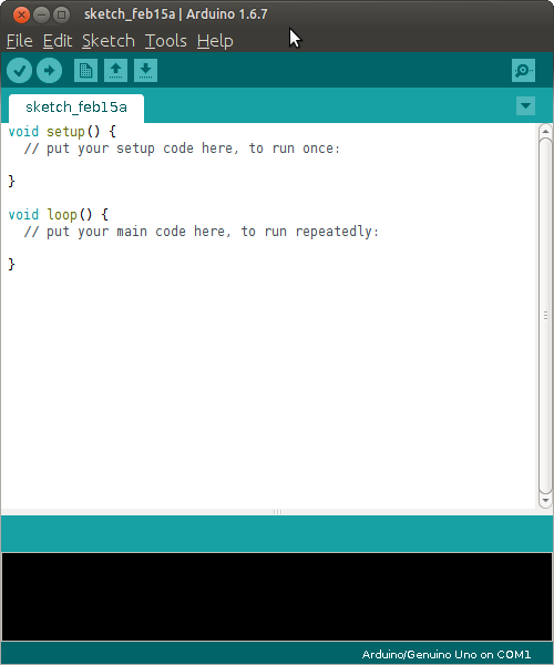
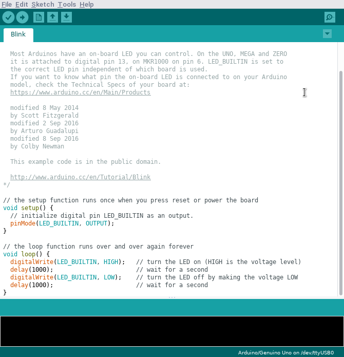
If you already have the Arduino IDE installed, open it. It looks like this:
2.1. Before running the first program
Everytime we want to program a different board, we need to tell the IDE where to find it and what kind is.
Select Board Type Arduino UNO
Under the Tools menu, find the Board submenu and navigate that to select Arduino (Genuino) UNO.
Select Correct Serial Port
Under the Tools menu again, find the Port submenu and choose the one your board is connected to. Some tips to find out which is which:- The name of your board may appear next to it.
- Unplug the Arduino and see which one disappears from the list.
2.2. Understanding the interface
The IDE has a code editor where you write your code to test. It also has some quick buttons and menus for various functions. When you test your code, there is a notification area and a status bar that give information about any errors.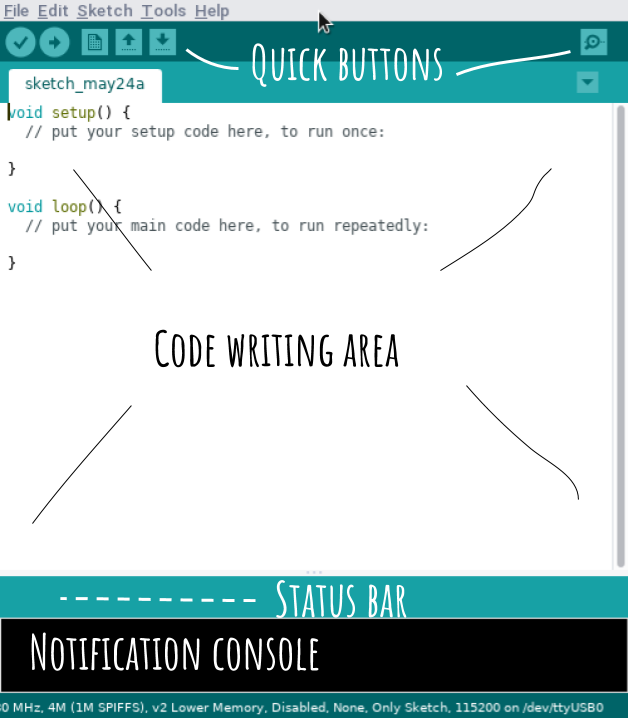
3. Blink a LED
A program designed for an Arduino board is called a sketch, and the process of transferring it to the board is called uploading.
We are now going to upload the first sketch. It will be one of the examples available on the IDE.
Open Blink sketch
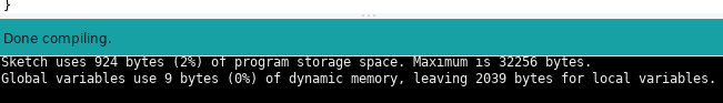
Verify the code
Upload to the board
Blink!
4. Deconstructing Blink
Sketches are written in text. When you select Verify, the Arduino software checks the program and translates it to Arduino-machine-language - which is not human-readable but is easy for the Arduino to understand.
Sketches themselves are written in C and/or C++,
which is a programming language that is very popular and powerful.

We will now take a closer look at the code itself.
/*
  Blink

  Turns an LED on for one second, then off for one second, repeatedly.

  Most Arduinos have an on-board LED you can control. On the UNO, MEGA and ZERO
  it is attached to digital pin 13, on MKR1000 on pin 6. LED_BUILTIN is set to
  the correct LED pin independent of which board is used.
  If you want to know what pin the on-board LED is connected to on your Arduino
  model, check the Technical Specs of your board at:
  https://www.arduino.cc/en/Main/Products

  modified 8 May 2014
  by Scott Fitzgerald
  modified 2 Sep 2016
  by Arturo Guadalupi
  modified 8 Sep 2016
  by Colby Newman

  This example code is in the public domain.

  http://www.arduino.cc/en/Tutorial/Blink
*/

// the setup function runs once when you press reset or power the board
void setup() {
  // initialize digital pin LED_BUILTIN as an output.
  pinMode(LED_BUILTIN, OUTPUT);
}

// the loop function runs over and over again forever
void loop() {
  digitalWrite(LED_BUILTIN, HIGH);   // turn the LED on (HIGH is the voltage level)
  delay(1000);                       // wait for a second
  digitalWrite(LED_BUILTIN, LOW);    // turn the LED off by making the voltage LOW
  delay(1000);                       // wait for a second
}
You may notice different parts of the code highlighted in different colours. This is automatic and helps the programmer understand the code more easily.
4.1. Comments
Let's take a look at the first part of the sketch.
/*
  Blink

  Turns an LED on for one second, then off for one second, repeatedly.

  Most Arduinos have an on-board LED you can control. On the UNO, MEGA and ZERO
  it is attached to digital pin 13, on MKR1000 on pin 6. LED_BUILTIN is set to
  the correct LED pin independent of which board is used.
  If you want to know what pin the on-board LED is connected to on your Arduino
  model, check the Technical Specs of your board at:
  https://www.arduino.cc/en/Main/Products

  modified 8 May 2014
  by Scott Fitzgerald
  modified 2 Sep 2016
  by Arturo Guadalupi
  modified 8 Sep 2016
  by Colby Newman

  This example code is in the public domain.

  http://www.arduino.cc/en/Tutorial/Blink
*//**/One-line comments
// the setup function runs once when you press reset or power the board
void setup() {
  // initialize digital pin LED_BUILTIN as an output.
  pinMode(LED_BUILTIN, OUTPUT);
}
The first line starts with
//4.2. Statements
We will now focus on two of the first lines of code:
  // initialize digital pin LED_BUILTIN as an output.
  pinMode(LED_BUILTIN, OUTPUT);
The first line is obviously a comment.
The second line is not a comment, it is just code. It is the first statement of the sketch. A statement is like a sentence for the Arduino and it always ends with a ;.
This statement is commanding the Arduino to set the mode of the Built-in LED to output.
You may be wondering now why we had to do this in the first place, since we have mentioned that LEDs are outputs. This is because the build-in LED is connected to a specific digital input/output port, pin 13. When using any digital pin in a program, we need to declare it as input or output. More on this on the next module.
| Function name |
Inputs | |||
|---|---|---|---|---|
| pinMode | ( | LED_BUILTIN, OUTPUT |
) | ; |
4.3. Functions
We will now take a step back, and look at the first line of code.
// the setup function runs once when you press reset or power the board
void setup() {
  // initialize digital pin LED_BUILTIN as an output.
  pinMode(LED_BUILTIN, OUTPUT);
}
We see that the
pinModevoid setup() {
...
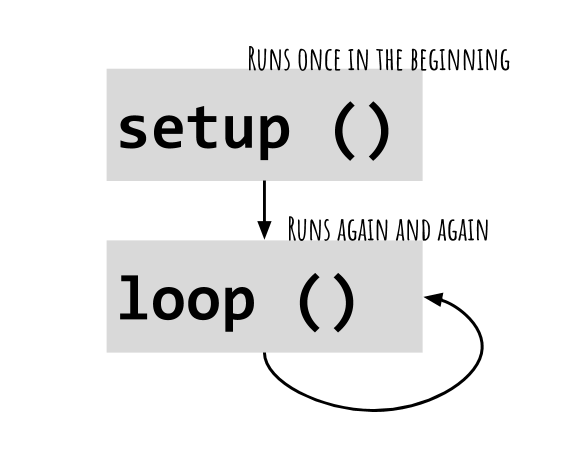
}These structures are called functions. In an Arduino sketch, these are the two basic sections: the setup() function and the loop() function.
void setup() {
...
}
void loop() {
...
}
Whatever is inside setup() happens once in the beginning of the program execution, followed by loop() which repeats over and over.
4.4. Inside loop()
First, let's take a look at what statements are inside the loop():
  digitalWrite(LED_BUILTIN, HIGH);   // turn the LED on (HIGH is the voltage level)
  delay(1000);                       // wait for a second
  digitalWrite(LED_BUILTIN, LOW);    // turn the LED off by making the voltage LOW
  delay(1000);                       // wait for a second
This is essentially the part of the program that describes blinking. We see that blinking is actually turning a LED on, waiting for a while, turning it off, waiting for a while again and then repeating from the top.
Let's take the statements one by one:
digitalWrite(LED_BUILTIN, HIGH); // turn the LED on (HIGH is the voltage level)
In an Arduino sketch, write means to set a value. digitalWrite() will set a value of HIGH or LOW. For the digital output pins of the Arduino, HIGH and LOW means turning them ON and OFF.
Notice that the way we use digitalWrite() looks similar to pinMode() that we saw earlier.
delay(1000); // wait for a secondThe delay() will pause the program, preventing the Arduino from executing the next command. The number in the parentheses is the amount of time it will wait in milliseconds.
1000 msec = 1 sec
The next statement is very similar to the first digitalWrite() in the program, however this time it sets the pin to LOW, turning the LED OFF.
5. Blink remix
Time to change something and see what happens!
Try the following exercises:
- Go to the Arduino IDE and change the delay from 1000 to 500 ms.
- What do you think it is going to happen? :-)
- Go crazy and change one of the comments.
- What do you think it is going to happen now? :-D
- Make the LED go ON for 100ms and OFF for 900ms.
- Make the LED go ON for 50ms and OFF for 50ms.
- Now 10ms ON and 10ms OF.
- What happened?