Sensing the analog world
| Ιστότοπος: | ΕΛ/ΛΑΚ Moodle |
| Μάθημα: | 3D printing with circuits and Arduino |
| Βιβλίο: | Sensing the analog world |
| Εκτυπώθηκε από: | Guest user |
| Ημερομηνία: | Τετάρτη, 15 Ιουλίου 2026, 11:06 PM |
Περιγραφή
Measuring the environment with 1024 bits.
1. The serial monitor
Keeping track of everything going on in your program can be an uphill
battle. The serial monitor is a way to check in on different spots in
your code by reporting back to the computer over the USB cable.
This circuit uses a button setup similar to the previous examples, but without a LED. Navigate to File >
Examples > 01.Basics > DigitalReadSerial and load the example sketch.

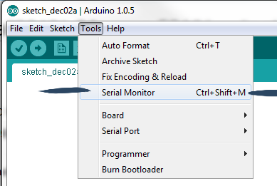
Upload this code to
your board and click the Serial Monitor button in the upper right of the
sketch window or go to Tools > Serial Monitor.
Serial.begin(); inside setup(). The number 9600 is the baud rate, or data speed, in bits per second (bps). Inside the loop(), we use Serial.print(); to send information to the serial port. Serial.println();
does the same thing, but prints on a new line. Serial.println(buttonState);2. Analog values
We've been talking about the Arduino as a platform to interact with the environment for quite a while now, but so far we have only experimented with digital, two-state control.
Time to open things up!
Digital values are great for a number of things, where the simplicity and elegance of on and off strives.
Analog values, on the other hand, can vary to a range. As humans, we sense the world as a stream of analog signals via sight, hearing etc. By using analog values with the Arduino, we can respond to user input in a complex fashion. You can control the brightness of an LED, setting it to shine brightly, grow dimmer, or show any range of values in between.
3. Reading the potentiometer
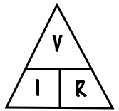
In the Electronics crash course we talked about alternating current vs. direct current and also introduced the potentiometer, a variable resistor. Remember that according to Ohm's law, resistance is proportionate to voltage.
Analog Inputs
To sense a gradually changing electrical signal, we'll use Arduino's
analog inputs, located on the left side of the board. These special pins
are connected to the Arduino's analog to digital converter (ADC),
equipped to convert an analog signal between 0V and 5V into a range of
numbers from 0-1023 (zero counts as a value).
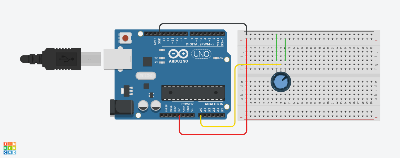
Now upload the following code to the Arduino:
int potPin = 0;

void setup()
{
  Serial.begin(9600);
}

void loop()
{
  int reading  = analogRead(potPin);
  Serial.println(reading);
  delay(500);
}
Turn the knob on the variable resistor and you will see the number change between 0 and 1023.
The Serial Monitor is
displaying the analog reading value from A0 using the line:
int reading = analogRead(potPin);The voltage at A0 is being transformed into a number between 0 and 1023.
4. Sensing light
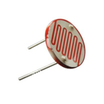
The photocell we will use in this module is of a type called a light dependent resistor, sometimes called an LDR. As the name suggests, these components act just like a resistor, except that the resistance changes in response to how much light is falling on them.
Hook it up to the Ohm-meter of the multimeter and guess what its range is!
The LDR isn’t very precise, so we cannot get a quantitative LUX reading
or anything like that. But it is good enough to tell the difference
between light and shadow, or know if the light in the room is on/off.
So if we just need to know if the light in the room has changed, or
someone walked by (casting a shadow) the LDR will do.
Connecting the LDR
The LDR changes its resistance with light so we can measure that
change using one of the Arduino’s analog pins. But to do that we need a
fixed resistor that we can use for that comparison. We
are using a 10K resistor.
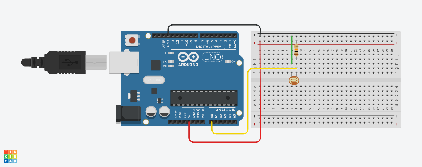
This circuit is called a voltage divider and divides the 5v between the LDR and the resistor. Then we measure how much voltage is on the LDR using the analog read on the Arduino, and we have the reading. The amount of that 5V that each part gets is proportional to its resistance.
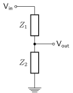
With the Arduino analogRead(), at 5V it would read 1023, and at 0v it read 0.
So if the the LDR and the resistor have the same resistance, the 5V is split evenly (2.5V), to each part. (analogRead of 512)
But if the LDR is hit with a ton of light and is reading only 1K of resistance, the 10K resistor is going to soak up 10 times as much of that 5V. So the LDR would only get .45V (analogRead of 92).
And if it is in a dark room, the LDR may be 40K or resistance, so the LDR will soak up 4 times as much of that 5V as the 10K resistor. So the LDR would get 4V (analogRead of 818).
int LDR_Pin = A0; //analog pin 0

void setup(){
Serial.begin(9600);
}

void loop(){
int LDRReading = analogRead(LDR_Pin);

Serial.println(LDRReading);
delay(250); //just here to slow down the output for easier reading
}