Input and output
| Site: | ΕΛ/ΛΑΚ Moodle |
| Course: | 3D printing with circuits and Arduino |
| Book: | Input and output |
| Printed by: | Guest user |
| Date: | Friday, 19 June 2026, 6:59 AM |
Description
Switches, speakers, LEDs, and flashing unicorns.
1. Digital Input/Output
In a sense, all these LEDs we have used so far acted as digital outputs. What else can be a digital output? Any device that can have two states: ON and OFF, HIGH and LOW, 5V and 0V.
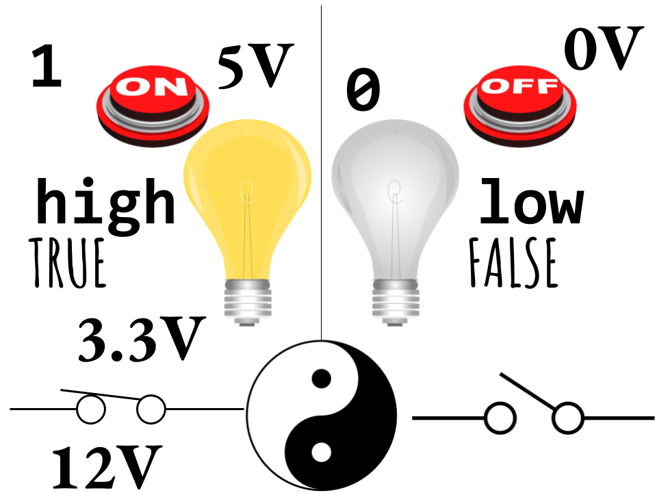
Output
So far we have not used any external signal with the Arduino as input to one of the pins. There are million of ways to trigger an electronic system, the most common being the switch.
When the switch is ON, it allows electricity flow in a circuit, and when it is OFF it does not. In Arduino, this translates to HIGH and LOW accordingly.
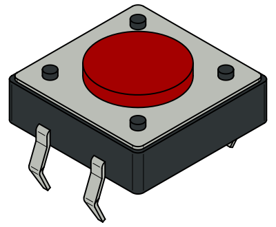
There are many types of switches around us. We will first experiment with buttons. The main input device of personal computers, the keyboard, is actually a set of switch buttons.
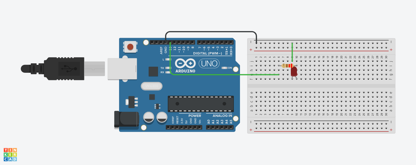
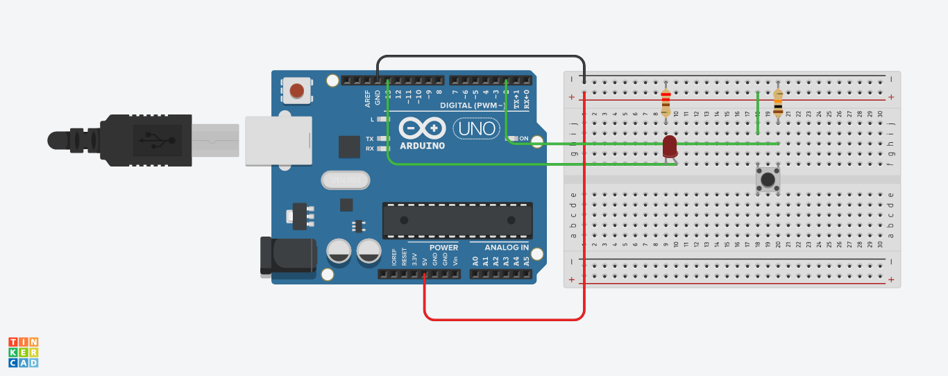
2. Add a button
The extra components we will need for this circuit are:
- One LED
- One 220Ω resistor (red, red, brown, gold)
- One 10kΩ resistor (brown, black, orange, gold)
- One pushbutton/tact switch


2.1. A look on the sketch
// constants won't change. They're used here to set pin numbers:
const int buttonPin = 2;     // the number of the pushbutton pin
const int ledPin =  13;      // the number of the LED pin

// variables will change:
int buttonState = 0;         // variable for reading the pushbutton status

void setup() {
  // initialize the LED pin as an output:
  pinMode(ledPin, OUTPUT);
  // initialize the pushbutton pin as an input:
  pinMode(buttonPin, INPUT);
}

void loop() {
  // read the state of the pushbutton value:
  buttonState = digitalRead(buttonPin);

  // check if the pushbutton is pressed. If it is, the buttonState is HIGH:
  if (buttonState == HIGH) {
    // turn LED on:
    digitalWrite(ledPin, HIGH);
  } else {
    // turn LED off:
    digitalWrite(ledPin, LOW);
  }
}
Let's now examine the code of the Button sketch.
Constants
const int buttonPin = 2; digitalRead()
buttonState = digitalRead(buttonPin);2.2. if...else statements
// check if the pushbutton is pressed. If it is, the buttonState is HIGH:
  if (buttonState == HIGH) {
    // turn LED on:
    digitalWrite(ledPin, HIGH);
  } else {
    // turn LED off:
    digitalWrite(ledPin, LOW);
  }
Inside the loop() function we have what is called a conditional statement. Conditional statements in programming allow something to happen/executed if a condition is met.
Some conditional statements in real life:
- If the birds are flying low, it is going to rain.
- If you turn on the radio, it will play music.
- If the light is red, the cars stop.
  if (some_condition) {
    // execute the following if the condition is TRUE
    do_this;
    and_this;
 } else {
   // execute the following if the condition is FALSE
   do_that;
  }
In the Button sketch, the if statement checks to see if buttonState is HIGH. If the condition is met, the
digitalWrite(ledPin, HIGH); digitalWrite(ledPin, LOW);One important thing to note is that
===Inside the if statement condition, only the following and their combinations can be used:
x == y (x is equal to y)
x != y (x is not equal to y)
x <  y (x is less than y)
x >  y (x is greater than y)
x <= y (x is less than or equal to y)
x >= y (x is greater than or equal to y)
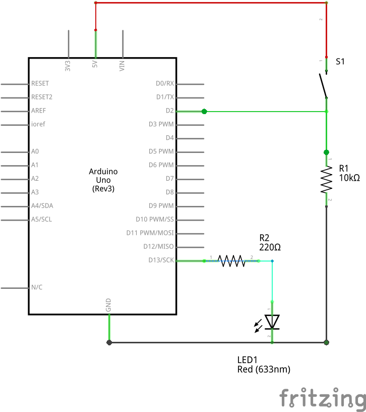
2.3. The pull-down resistor
You might now be wondering what the purpose of that big 10k resistor was.
At rest, the switch pins are not connected to one another. Pin 2 is
connected through a 10K resistor to ground (-). When the button is
pressed, the switch pins are connected, which allows pin 2 to be
connected to HIGH (5V/+), with no resistor. Since electricity takes the path
of least resistance, the pin will sense the connection to (+)
strongly, and ignore the weak (10K) connection to ground. But when no other
signal is present (when the switch isn't being pressed), that weak
connection to ground is all the pin can sense.

So the resistor is "pulling
the pin down" to ground and so it's called a pull-down resistor.
Without one, pin 2 would be not connected to anything until the button
is pressed. This is called "floating", and can result in random noise
from static electricity and electromagnetic interference.
You can test this by measuring the air's voltage levels with a multimeter!
Similarly a resistor can be used to tie a pin to (+), which is called a pull-up resistor.
Arduino pins have built-in pull-up resistors on many of the pins (tiny ones, inside the chip just for this purpose), and you can access one by enabling it in the setup:
pinMode(buttonPin, INPUT_PULLUP);
3. Add a speaker
In this circuit, the button, LED, resistors, and jumpers will stay in the same place. You are simply adding a 8Ω speaker; everything else remains the same.
Before making changes to your circuit, remove it from power.
Attach one end of the speaker to pin 11 and the other to ground. For this example, it doesn't matter which end goes where.

Now let's take a look at the code.
First up, we need to add a variable for the speaker pin (11):
const int speakerPin = 11; //the number of the speaker pinThis will go on the top, outside setup() and loop().
Next, we shall initialise speakerPin in setup():
pinMode(speakerPin, OUTPUT);Finally, we need to output the buttonState value also to the speaker. We will do so by using the Arduino functions called tone() and noTone().
void loop() {
  // read the state of the pushbutton value:
  buttonState = digitalRead(buttonPin);

  // check if the pushbutton is pressed. If it is, the buttonState is HIGH:
  if (buttonState == HIGH) {
    // turn LED on:
    digitalWrite(ledPin, HIGH);
    tone(speakerPin, 440);
  } else {
    // turn LED off:
    digitalWrite(ledPin, LOW);
    noTone(speakerPin);
  }
}
tone() will generate a note or tone that can play through the speaker. When you use the tone() function, you need to tell Arduino on which pin to generate a tone and what note to play.
tone(which_pin, tone_frequency);We define notes by their frequency value. 440Hz famously is the note A. You can find a detailed list of acceptable notes for tone() here.
noTone() on the other hand stops the sound from being played on the pin specified. In this case, that’s speakerPin, which stores the value of the pin that has the speaker attached to it. If you leave out noTone() , then your note will play continuously once you press the button the first time.
4. Piano on the way
The final code looks like this:
// constants won't change. They're used here to set pin numbers:
const int buttonPin = 2;     // the number of the pushbutton pin
const int ledPin =  13;      // the number of the LED pin
const int speakerPin = 11; //the number of the speaker pin

// variables will change:
int buttonState = 0;         // variable for reading the pushbutton status

void setup() {
  // initialize the LED pin as an output:
  pinMode(ledPin, OUTPUT);
  // initialize the pushbutton pin as an input:
  pinMode(buttonPin, INPUT);
  pinMode(speakerPin, OUTPUT);
}

void loop() {
  // read the state of the pushbutton value:
  buttonState = digitalRead(buttonPin);

  // check if the pushbutton is pressed. If it is, the buttonState is HIGH:
  if (buttonState == HIGH) {
    // turn LED on:
    digitalWrite(ledPin, HIGH);
    tone(speakerPin, 440);
  } else {
    // turn LED off:
    digitalWrite(ledPin, LOW);
    noTone(speakerPin);
  }
}
We are now going to add one more button to the circuit, to play a different note once pressed. We will need one more pushbutton and one more 10kΩ resistor.
The setup of this button will the same as first button, alas the new button will be
attached to a different pin on the Arduino (3).
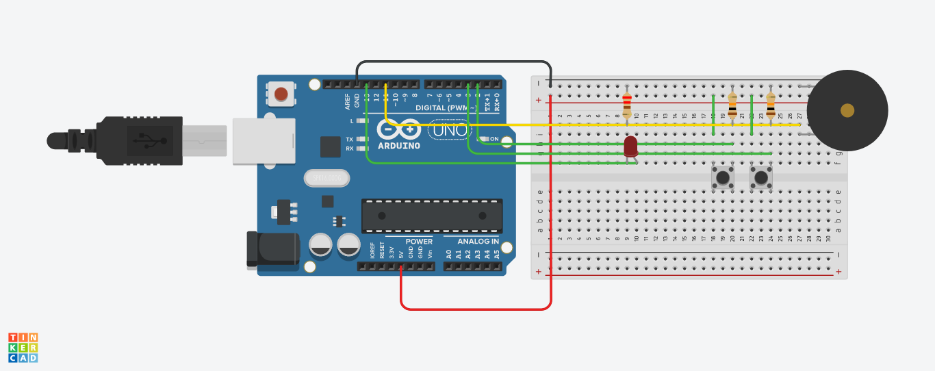
First we add variables for the new button:
// constants won't change. They're used here to set pin numbers:
const int buttonPin = 2;     // the number of the pushbutton pin
const int buttonPin = 3;     // the number of the new pushbutton pin!
const int ledPin =  13;      // the number of the LED pin
const int speakerPin = 11; //the number of the speaker pin

// variables will change:
int buttonState = 0;         // variable for reading the pushbutton status
int buttonState2 = 0;         // variable for reading the new pushbutton status!
And then we initialise pin 3 as input:
void setup() {
  // initialize the LED pin as an output:
  pinMode(ledPin, OUTPUT);
  // initialize the pushbutton pins as an input:
  pinMode(buttonPin, INPUT);
  pinMode(buttonPin2, INPUT); //tadah!
  // initialise the speaker pin as output:
  pinMode(speakerPin, OUTPUT);
}
4.1. else if statement
From the new variables that we declared, it is easy to assume that we are reading the value of buttonPin2 with digitalRead() and storing it in buttonState2.
We also need a new conditional statement. In order for it to make sense within the existing program, we will use an else if.
The rough idea of the sketch goes like this;
if (button 1 is pressed) {
    play A;
    turn on LED;
}
else if (button 2 is pressed) {
    play D;
    turn on LED;
}
else {
    play nothing;
    turn off LED;
}
So the if condition will be checked first. If it is true, the speaker will play a perfect A and the LED turns on. If it is false, the else if statement will be examined. If that is true, the speaker will play an almost perfect D and turn on the LED. If it is false all sounds and lights off. Repeat the loop forever.
Compose the sketch for the 2-piece piano!
4.2. 2-button sketch
// constants won't change. They're used here to set pin numbers:
const int buttonPin = 2;     // the number of the pushbutton pin
const int buttonPin2 = 3;     // the number of the pushbutton pin
const int ledPin =  13;      // the number of the LED pin
const int speakerPin = 11; //the number of the speaker pin

// variables will change:
int buttonState = 0;         // variable for reading the pushbutton status
int buttonState2 = 0;         // variable for reading the pushbutton status

void setup() {
  // initialize the LED pin as an output:
  pinMode(ledPin, OUTPUT);
  // initialize the pushbutton pins as inputs:
  pinMode(buttonPin, INPUT);
  pinMode(buttonPin2, INPUT);
  // initialise the speaker pin as output:
  pinMode(speakerPin, OUTPUT);
}

void loop() {
  // read the state of the pushbuttons value:
  buttonState = digitalRead(buttonPin);
  buttonState2 = digitalRead(buttonPin2);

  // check if the first pushbutton is pressed. If it is, the buttonState is HIGH:
  if (buttonState == HIGH) {
    // turn LED on:
    digitalWrite(ledPin, HIGH);
    tone(speakerPin, 440);
  }
  else if (buttonState2 == HIGH) {
    digitalWrite(ledPin, HIGH);
    tone(speakerPin, 293);
  }
  else {
    // turn LED off:
    digitalWrite(ledPin, LOW);
    noTone(speakerPin);
  }
}