Infinite* colours
| Site: | ΕΛ/ΛΑΚ Moodle |
| Course: | 3D printing with circuits and Arduino |
| Book: | Infinite* colours |
| Printed by: | Guest user |
| Date: | Friday, 26 June 2026, 10:50 PM |
Description
Analog values as output in the colour spectrum.
1. RGB LEDs
In this module, we are going to control the colour of RGB LEDs with the Arduino.
At first glance, RGB (Red, Green, Blue) LEDs look just like regular LEDs, however, inside the usual LED package, there are actually three LEDs, one red, one green and one blue. By controlling the brightness of each of the individual LEDs we can mix pretty much any colour.
However, the Arduino is only capable of outputing digital signals; either 5V or 0V. So, how are we going to output the analog value of brightness?
2. Pulse width modulation
So how does PWM work? Imagine turning the lights on and then off in your room. The room looks bright for a moment, and then dark again. If you continue to flip the light switch back and forth at a slow rate, the room just appears to be bright, then dark, over and over.
But something strange happens when you flip the light switch faster and faster. Rather than just appearing bright followed by dark, your room will have a light level somewhere in between bright and dark. In fact, the room will also appear brighter if you leave the light on for slightly more time than you leave it off. Your room will have a light level that is the average brightness that is dependent on the percentage of time that the light is on in relation to the percentage of time the light is off.
PWM uses a technique similar to flipping the light switch to create a brighter or dimmer light level. When you use PWM on the Arduino, the level of voltage on the PWM pin is switched on and off at various rates at regular intervals. It is sometimes 0 volts, and sometimes 5 volts.
Pulse Width Modulation, or PWM, is a technique for getting analog results with digital means. Digital control is used to create a square wave, a signal switched between on and off. This on-off pattern can simulate voltages in between full on (5 Volts) and off (0 Volts) by changing the portion of the time the signal spends on versus the time that the signal spends off. The duration of "on time" is called the pulse width. To get varying analog values, you change, or modulate, that pulse width. If you repeat this on-off pattern fast enough with an LED for example, the result is as if the signal is a steady voltage between 0 and 5v controlling the brightness of the LED.

By varying the amount of time the pin is turned on and off, the Arduino creates an average voltage value between 0 and 5V.

Not all digital pins can be used with PWM. The ones that can are marked by he ~ symbol on the Arduino: pins 3, 5, 6, 9, 10, 11.
analogWrite() is function that can be used with these pins to output a variable amount of power with PWM. We will use it to control brightness levels of the appropriate LEDs.
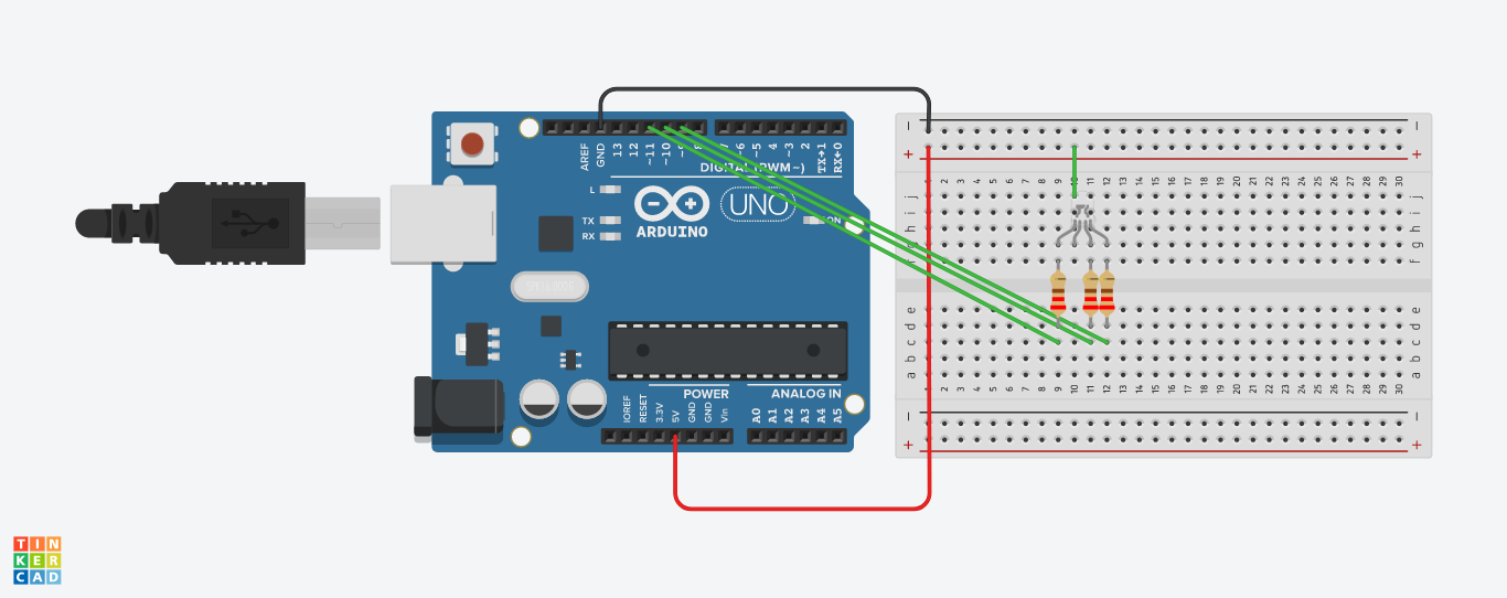
3. Common anode
The RGB LEDs we are using have a common anode.
There is one lead going to the negative connection of each of the single LEDs within the package and a single lead that is connected to all three positive sides of the LEDs.
The common anode of the LED package is longest of the four
leads. This lead will be connected to 5V.
Each LED inside the package requires its own current limiting resistor. The three negative leads of the LEDs (one red, one green and one blue) are connected to Arduino output pins using these resistors.
4. Colour in the naked eye
For any light source that emits light directly to our eyes, the colour that is perceived by our brain has three basic components, some amount of red, green and blue. Variations in their amount help us to create various colours.

If we set the brightness of all three LEDs to be the same, then the
overall colour of the light will be white. If we turn off the blue LED,
so that just the red and green LEDs are the same brightness, then the
light will appear yellow.
We can control the brightness of each
of the red, green and blue parts of the LED separately, making it
possible to mix any colour we like.
Black is not so much a
color as an absense of light. So the closest we can come to black with
our LED is to turn off all three colors.
5. analogWrite()
This is the code we are going to use:
const int redPin = 11;
const int greenPin = 10;
const int bluePin = 9;

void setup()
{
  pinMode(redPin, OUTPUT);
  pinMode(greenPin, OUTPUT);
  pinMode(bluePin, OUTPUT);
}

void loop()
{
  setColor(255, 0, 0);  // red
  delay(1000); // pause for a second
  setColor(0, 255, 0);  // green
  delay(1000);
  setColor(0, 0, 255);  // blue
  delay(1000);
  setColor(255, 255, 0);  // yellow
  delay(1000);
  setColor(80, 0, 80);  // purple
  delay(1000);
  setColor(0, 255, 255);  // aqua
  delay(1000);
}

void setColor(int red, int green, int blue)
{
  red = 255 - red;
  green = 255 - green;
  blue = 255 - blue;
  analogWrite(redPin, red);
  analogWrite(greenPin, green);
  analogWrite(bluePin, blue);
}
As you may notice, this sketch has one more function written called setColor.
void setColor(int red, int green, int blue)
{
  red = 255 - red;
  green = 255 - green;
  blue = 255 - blue;
  analogWrite(redPin, red);
  analogWrite(greenPin, green);
  analogWrite(bluePin, blue);
}
This function takes three arguments, one for the brightness of the red,
green and blue LEDs. In each case the number will be in the range 0 to
255, where 0 means off and 255 means maximum brightness. The function
then calls analogWrite to set the brightness of each LED. Since we are using a common anode RGB LED, we also need to change the
analog write values so that the colour is subtracted from 255.
6. Hex colours
Colours in programming are often represented as a 'hex' number. For example the colour red has the number #FF0000. You can find the numbers associated
with a particular colour using tables like these:
The six digits of the number are actually three pairs of numbers; the first pair being the red component of the color, the next two digits the green part and the final pair the blue part. Red is #FF0000, because its maximum red (FF is 255 in hex) and it has no green or blue part.
Let's try and make the color indigo (#4B0082).
The red, green and blue parts of indigo are (in hex) 4B, 00 and 82 respectively. We can plug those into the 'setColor' function like this:
setColor(0x4B, 0x0, 0x82); // indigoTry adding a few colors of your own to the 'loop' function. Don't forget to add a delay after each one.