Sensor breakouts
| Site: | ΕΛ/ΛΑΚ Moodle |
| Course: | 3D printing with circuits and Arduino |
| Book: | Sensor breakouts |
| Printed by: | Guest user |
| Date: | Friday, 26 June 2026, 2:24 PM |
Description
Reading data sheets, black-boxing sensors
1. Identifying electronic parts
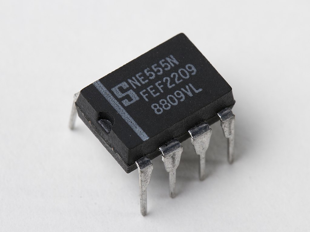
Electronic data sheets document the behaviour, function, and limitations of electronic components. They have a tremendous amount of information, from operating temperature and behaviour and suggested wiring diagrams, to material make-up and industrial application.
2. Breakout boards
So far we have constructed our own sensors with variable resistors inside voltage dividers. We will now explore some manufactured breakout boards that will output their measurements to Arduino.
In fact this is the basic concept of breakout boards; to take more complex electrical components, such as integrated circuits (also known as ICs), components and make them easy to use.
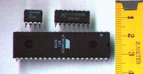
These more complex circuits (integrated or not), have many connections and pins, doing a multitude of things, such as for supply
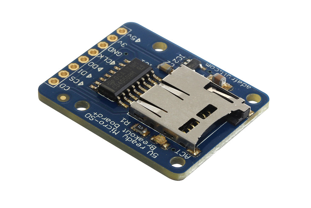
power, ground, input and output. A breakout board 'breaks out' these pins onto a printed circuit board
that has its own pins that are spaced perfectly for a solderless
breadboard, giving you easy access to use the integrated circuit.
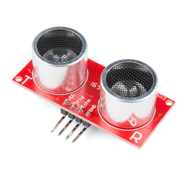
There are all type of breakout boards – but most of them are for
different types of sensors, for example ultrasonic
distance sensors, temperature or humidity sensors, soil moisture sensors etc.
3. Sensor technology
Sensors are devices that allow any electronic equipment to perceive the physical world. Sensors help electronics see, listen to, smell, taste and touch. All these are realised by a sensor interface which translates physical world signals to a form that electronics can understand.
Essentially, sensors transform non-electrical or chemical quantities to electrical signals. What types of measurements are we talking about?
- Thermal: temperature, heat, heat flow etc.
- Mechanical: force, pressure, speed, flex, acceleration, position etc.
- Chemical: concentration etc.
- Magnetic: magnetic field strength etc.
- Radiation: wavelength, intensity and in general characteristics of electromagnetic waves.
- Electrical: voltage, current, load etc.
4. Sensing movement, sound and light.
The sensor breakout boards we are going to use in this module are the following:
This sensor senses light more accurately than the LDR photocell we used before, using a phototransistor. It has one analog out pin.

Passive infrared (PIR) sensor HC-SR501
This is an infrared motion detector, that gives a digital output.
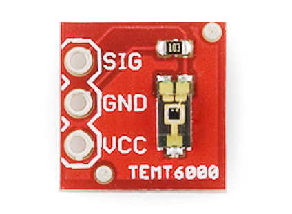
5. TEMT6000
When we need to sense ambient brightness with better precision than the trusty photoresistor and without adding complexity to your project, a TEMT6000 ambient light sensor is what we are looking for.
The TEMT6000 is supposed to be adapted to the sensitivity of the human eye. It works very well reacting to very small changes in a large range of brightnesses. Because it is meant to mimic the human eye, it does not react well to IR or UV light, though.

Hooking It Up
This is an incredibly simple part, we just connect power and ground, and
the signal pin to our favourite analog input and the
sensor will output an analog voltage, that ramps up when it gets brighter.

Code
This just reports the reading from the sensor to the serial terminal: 0-1023 with 1023 being very bright, and 0 being very dark.
const int temt6000Pin = 0;

void setup() {
Serial.begin(9600);
}

void loop() {
int value = analogRead(temt6000Pin);
Serial.println(value);

delay(100); //only here to slow down the output so it is easier to read
}
6. PIR
PIR sensors allow to sense motion, almost always used
to detect whether a human has moved in or out of the sensor's range. They
are small, inexpensive, low-power, easy to use and don't wear out. For
that reason they are commonly found in appliances and gadgets used in
homes or businesses. They are often referred to as PIR, "Passive
Infrared", "Pyroelectric", or "IR motion" sensors.
PIRs are basically made of a pyroelectric sensor
(which you can see above as the round metal can with a rectangular
crystal in the center), which can detect levels of infrared radiation.
Everything emits some low level radiation, and the hotter something is,
the more radiation is emitted. The sensor in a motion detector is
actually split in two halves. The reason for that is that we are looking
to detect motion (change) not average IR levels. The two halves are
wired up so that they cancel each other out. If one half sees more or
less IR radiation than the other, the output will swing high or low.
For many basic projects or products that need to detect when a person has left or entered the area, or has approached, PIR sensors are great. They are low power and low cost, pretty rugged, have a wide lens range, and are easy to interface with. Note that PIRs won't tell how many people are around or how close they are to the sensor, the lens is often fixed to a certain sweep and distance (although it can be hacked somewhere) and they are also sometimes set off by house pets. Experimentation is key!


How does it work?
The PIR sensor itself has two slots in it, each slot is made of a special material that is sensitive to IR. The lens used here is not really doing much and so we see that the two slots can 'see' out past some distance (basically the sensitivity of the sensor). When the sensor is idle, both slots detect the same amount of IR, the ambient amount radiated from the room or walls or outdoors. When a warm body like a human or animal passes by, it first intercepts one half of the PIR sensor, which causes a positive differential change between the two halves. When the warm body leaves the sensing area, the reverse happens, whereby the sensor generates a negative differential change. These change pulses are what is detected.

PIR sensors are rather generic and for the most part vary only in price
and sensitivity. Most of the real magic happens with the optics. This is
a pretty good idea for manufacturing: the PIR sensor and circuitry is
fixed and costs a few dollars. The lens costs only a few cents and can
change the breadth, range, sensing pattern, very easily.
In the
diagram above, the lens is just a piece of plastic, but that means that
the detection area is just two rectangles. Usually we'd like to have a
detection area that is much larger. To do that, we use a simple lens
such as those found in a camera: they condenses a large area (such as a
landscape) into a small one (on film or a CCD sensor). For reasons that
will be apparent soon, we would like to make the PIR lenses small and
thin and moldable from cheap plastic, even though it may add distortion.
OK, so now we have a much larger range. However, remember that we actually have two sensors, and more importantly we dont want two really big sensing-area rectangles, but rather a scattering of multiple small areas. So what we do is split up the lens into multiple section. The different faceting and sub-lenses create a range of detection areas, interleaved with each other. That's why the lens centers in the facets above are 'inconsistent' - every other one points to a different half of the PIR sensing element
Hook-up

Most PIR modules have a 3-pin connection at the side or bottom. The
pinout may vary between modules so triple-check the pinout! One pin will be ground,
another will be signal and the final one will be power. In the HC-SR501 model power is 5-20VDC input.
Connect the PIR sensor to pin 2 and run the following code:
/*
 * PIR sensor tester
 */

int inputPin = 2;               // choose the input pin (for PIR sensor)
int pirState = LOW;             // we start, assuming no motion detected
int val = 0;                    // variable for reading the pin status

void setup() {
  pinMode(inputPin, INPUT);     // declare sensor as input
  Serial.begin(9600);
}

void loop(){
  val = digitalRead(inputPin);  // read input value
  if (val == HIGH) {            // check if the input is HIGH
    if (pirState == LOW) {
      // we have just turned on
      Serial.println("Motion detected!");
      // We only want to print on the output change, not state
      pirState = HIGH;
    }
  } else {
    if (pirState == HIGH){
      // we have just turned of
      Serial.println("Motion ended!");
      // We only want to print on the output change, not state
      pirState = LOW;
    }
  }
}
Adjustments
decreases (about 3 meters).
◦ Adjust the delay potentiometer clockwise rotation sensor the delay lengthened (300s), on the contrary, shorten the induction delay (5s).
Applications
One of the most popular uses for PIR sensors are as security alarms. Above and below though, you can see a few more artistic takes.