From stick to strip
| Site: | ΕΛ/ΛΑΚ Moodle |
| Course: | 3D printing with circuits and Arduino |
| Book: | From stick to strip |
| Printed by: | Guest user |
| Date: | Saturday, 1 August 2026, 2:54 PM |
Description
Going big with addressable LEDs.
1. Powering strips
You can easily see by now that the example sketches used in the previous module are easily adapted for strips with more addressable LEDs.
However, the Arduino output pins do not provide enough current to drive a strip of LEDs. This is why we will be using a separate DC supply for the 1m strips we are going to connect to the Arduino UNO.
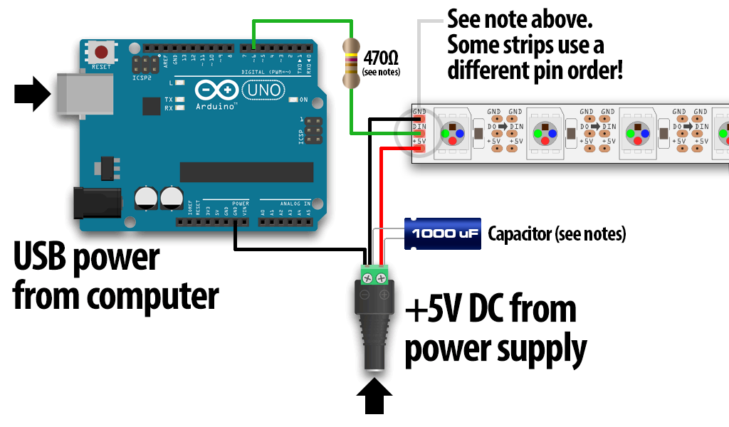
Identify the “input” end of your strip, pixel(s) or other
device; it will be labeled “DIN” or “DI” (data
input).
Then, connect
the +5V input on the strip to the + (positive) terminal on the power
supply (don’t connect to the Arduino), DIN to digital pin 6 on the
Arduino, and – (minus or GND) on the strip must connect to both the minus (–) terminal on the DC supply and a GND pin on the Arduino.
2. Good practices
- Try to minimize the distance between the Arduino and first pixel, so the signal is clear. A meter or two is usually no problem. Much longer and things can become unreliable.
- Avoid connecting NeoPixels to a live circuit. If you simply must, always connect ground first, then +5V, then data. Disconnect in the reverse order.
- If powering the pixels with a separate supply, apply power to the pixels before applying power to the microcontroller.
- Observe the same precautions as you would for any static-sensitive part; ground yourself before handling, etc.
- NeoPixels don’t care what end they receive power from. Though data moves in only one direction, electricity can go either way. You can connect power at the head, the tail, in the middle, or ideally distribute it to several points.
For best color consistency, aim for 1 meter or less distance from any
pixel to a power connection. With larger NeoPixel setups, think of power
distribution as branches of a tree rather than one continuous line.
3. The FastLED library
The FastLED library is just another library for addressable LEDs in Arduino.
Download it using the Arduino IDE:
Go to Sketch > Include Library > Manage Library in the Arduino IDE men.
Search for FASTLed library, select and install.
You can include it in any sketch also by using the menu: Sketch > Include Library > FastLED.
Here is a demo sketch using the library:
#include "FastLED.h"


#if defined(FASTLED_VERSION) && (FASTLED_VERSION < 3001000)
#warning "Requires FastLED 3.1 or later; check github for latest code."
#endif

#define DATA_PIN    6
#define LED_TYPE    WS2811
#define COLOR_ORDER GRB
#define NUM_LEDS    60
CRGB leds[NUM_LEDS];

#define BRIGHTNESS          96
#define FRAMES_PER_SECOND  80

void setup() {
  delay(3000); // 3 second delay for recovery

  // tell FastLED about the LED strip configuration
  FastLED.addLeds<LED_TYPE,DATA_PIN,COLOR_ORDER>(leds, NUM_LEDS).setCorrection(TypicalLEDStrip);
  //FastLED.addLeds<LED_TYPE,DATA_PIN,CLK_PIN,COLOR_ORDER>(leds, NUM_LEDS).setCorrection(TypicalLEDStrip);

  // set master brightness control
  FastLED.setBrightness(BRIGHTNESS);
}


// List of patterns to cycle through.  Each is defined as a separate function below.
typedef void (*SimplePatternList[])();
SimplePatternList gPatterns = { rainbow, rainbowWithGlitter, confetti, sinelon, juggle, bpm };

uint8_t gCurrentPatternNumber = 0; // Index number of which pattern is current
uint8_t gHue = 0; // rotating "base color" used by many of the patterns

void loop()
{
  // Call the current pattern function once, updating the 'leds' array
  gPatterns[gCurrentPatternNumber]();

  // send the 'leds' array out to the actual LED strip
  FastLED.show();
  // insert a delay to keep the framerate modest
  FastLED.delay(1000/FRAMES_PER_SECOND);

  // do some periodic updates
  EVERY_N_MILLISECONDS( 20 ) { gHue++; } // slowly cycle the "base color" through the rainbow
  EVERY_N_SECONDS( 10 ) { nextPattern(); } // change patterns periodically
}

#define ARRAY_SIZE(A) (sizeof(A) / sizeof((A)[0]))

void nextPattern()
{
  // add one to the current pattern number, and wrap around at the end
  gCurrentPatternNumber = (gCurrentPatternNumber + 1) % ARRAY_SIZE( gPatterns);
}

void rainbow()
{
  // FastLED's built-in rainbow generator
  fill_rainbow( leds, NUM_LEDS, gHue, 7);
}

void rainbowWithGlitter()
{
  // built-in FastLED rainbow, plus some random sparkly glitter
  rainbow();
  addGlitter(80);
}

void addGlitter( fract8 chanceOfGlitter)
{
  if( random8() < chanceOfGlitter) {
    leds[ random16(NUM_LEDS) ] += CRGB::White;
  }
}

void confetti()
{
  // random colored speckles that blink in and fade smoothly
  fadeToBlackBy( leds, NUM_LEDS, 10);
  int pos = random16(NUM_LEDS);
  leds[pos] += CHSV( gHue + random8(64), 200, 255);
}

void sinelon()
{
  // a colored dot sweeping back and forth, with fading trails
  fadeToBlackBy( leds, NUM_LEDS, 20);
  int pos = beatsin16( 13, 0, NUM_LEDS-1 );
  leds[pos] += CHSV( gHue, 255, 192);
}

void bpm()
{
  // colored stripes pulsing at a defined Beats-Per-Minute (BPM)
  uint8_t BeatsPerMinute = 62;
  CRGBPalette16 palette = PartyColors_p;
  uint8_t beat = beatsin8( BeatsPerMinute, 64, 255);
  for( int i = 0; i < NUM_LEDS; i++) { //9948
    leds[i] = ColorFromPalette(palette, gHue+(i*2), beat-gHue+(i*10));
  }
}

void juggle() {
  // eight colored dots, weaving in and out of sync with each other
  fadeToBlackBy( leds, NUM_LEDS, 20);
  byte dothue = 0;
  for( int i = 0; i < 8; i++) {
    leds[beatsin16( i+7, 0, NUM_LEDS-1 )] |= CHSV(dothue, 200, 255);
    dothue += 32;
  }
}
4. Temperature and humidity sensor
The DHT11 sensor is a Digital Temperature and Humidity sensor which can be connected and send environmental data to the Arduino.
The breakout board gives a digital output that is proportional to temperature and humidity measured by the sensor.
- Temperature range 0 / +50°C ±2°C
- Humidity range 20-90%RH ±5%RH

// Example testing sketch for various DHT humidity/temperature sensors
// Written by ladyada, public domain

#include "DHT.h"

#define DHTPIN 2     // what digital pin we're connected to

// Uncomment whatever type you're using!
#define DHTTYPE DHT11   // DHT 11
//#define DHTTYPE DHT22   // DHT 22  (AM2302), AM2321
//#define DHTTYPE DHT21   // DHT 21 (AM2301)

// Connect pin 1 (on the left) of the sensor to +5V
// NOTE: If using a board with 3.3V logic like an Arduino Due connect pin 1
// to 3.3V instead of 5V!
// Connect pin 2 of the sensor to whatever your DHTPIN is
// Connect pin 4 (on the right) of the sensor to GROUND
// Connect a 10K resistor from pin 2 (data) to pin 1 (power) of the sensor

// Initialize DHT sensor.
// Note that older versions of this library took an optional third parameter to
// tweak the timings for faster processors.  This parameter is no longer needed
// as the current DHT reading algorithm adjusts itself to work on faster procs.
DHT dht(DHTPIN, DHTTYPE);

void setup() {
  Serial.begin(9600);
  Serial.println("DHTxx test!");

  dht.begin();
}

void loop() {
  // Wait a few seconds between measurements.
  delay(2000);

  // Reading temperature or humidity takes about 250 milliseconds!
  // Sensor readings may also be up to 2 seconds 'old' (its a very slow sensor)
  float h = dht.readHumidity();
  // Read temperature as Celsius (the default)
  float t = dht.readTemperature();
  // Read temperature as Fahrenheit (isFahrenheit = true)
  float f = dht.readTemperature(true);

  // Check if any reads failed and exit early (to try again).
  if (isnan(h) || isnan(t) || isnan(f)) {
    Serial.println("Failed to read from DHT sensor!");
    return;
  }

  // Compute heat index in Fahrenheit (the default)
  float hif = dht.computeHeatIndex(f, h);
  // Compute heat index in Celsius (isFahreheit = false)
  float hic = dht.computeHeatIndex(t, h, false);

  Serial.print("Humidity: ");
  Serial.print(h);
  Serial.print(" %\t");
  Serial.print("Temperature: ");
  Serial.print(t);
  Serial.print(" *C ");
  Serial.print(f);
  Serial.print(" *F\t");
  Serial.print("Heat index: ");
  Serial.print(hic);
  Serial.print(" *C ");
  Serial.print(hif);
  Serial.println(" *F");
}
5. The serial plotter
We will now amend the previous sketch in order to plot temperature and heat index on the computer offline:
#include "DHT.h"
#define DHTPIN 2     // what digital pin we're connected to

#define DHTTYPE DHT11   // DHT 11
DHT dht(DHTPIN, DHTTYPE);

void setup() {
  Serial.begin(9600);
  Serial.println("DHTxx test!");
  dht.begin();
}

void loop() {
  // Wait a few seconds between measurements.
  delay(2000);

  // Sensor readings may also be up to 2 seconds 'old' (its a very slow sensor)
  // Read temperature as Celsius (the default)
  float t = dht.readTemperature();

  // Check if any reads failed and exit early (to try again).
  if (isnan(t)) {
    return;
  }
  Serial.println(t);

}
Now open Tools > Serial Plotter and see the temperature plot of the real-time sensor data. This feature is very handy when debugging sensors with Arduino.
You can also plot more than one variables at a time, by seperating them with a
Serial.print(" ");