Book
Day 8 - Section 1 - Controlling the colors
Day 8 - Section 1 - Controlling the colors
Completion requirements
View
After the completion of this section the students will be able to:
- describe the RGB color model
- state the difference between an RGB LED and a single color LED
- distinguish and use the legs of an RGB LED
- create a circuit with an RGB LED
- program the NodeMCU to change the color of an RGB LED with their smartphone
- create a ZeRGBa project to their smartphone
Changing colors on an RGB LED using Blynk
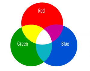
For any light source that emits light directly to our eyes, the color that is perceived by our brain has three basic components, some amount of red, green and blue. Variations in their amount help us to create various colors.
An RGB led is a single LED which provides us all three kinds of colors. They come in two forms: common cathode (one which we’ll be talking about in this project) and common anode. Common cathode has a common GND pin for all three colors. Here’s a picture of this and its pins-colors matching:

Actually, there are three LEDs, one red, one green and yes, one blue in one package. By controlling the amount of each of the individual LEDs you can mix pretty much any color you want.
You can play with the amounts of basic colors that you need in order to create a new color here:
As we have discussed in previous sections the digital ports can have only one of the two values: 0 or 1, TRUE or FALSE, ON or OFF. So, it is clear that we could not control the amount of light that any of the individual leds emits by connecting its legs to digital ports.

Here is a problem, that is fortunately solved and the solution is called PWM. Pulse Width Modulation, or PWM, is a technique for getting analog results with digital means. Digital control is used to create a square wave, a signal switched between on and off.

This on-off pattern can simulate voltages in between full on (3.3 Volts) and off (0 Volts) by changing the portion of the time the signal spends on versus the time that the signal spends off. The duration of "on time" is called the pulse width. To get varying analog values, you change, or modulate, that pulse width. If you repeat this on-off pattern fast enough with an LED for example, the result is as if the signal is a steady voltage between 0 and 3.3v controlling the brightness of the LED.
So in our case we choose three of the digital pins (D1, D2, D3) to connect the legs of Red, Green and Blue respectively. The cathode leg goes to GND pin. The diagram is as below:

Then, create a new Project in Blynk app named "RGB LED". The auth key will be sent to your email address. You will need it later.
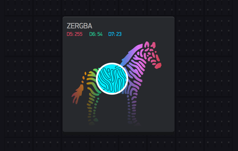
Place the ZeRGBa widget on the desktop of the project and adjust it based on the following screenshots:

The final step is to create the code that will transfer our (color) commands from Blynk to the RGB LED. We just need the default Blynk program that we used on a previous section. So, go to File->Examples->Blynk-Boards_Wifi->Esp8266Standalone

An RGB led is a single LED which provides us all three kinds of colors. They come in two forms: common cathode (one which we’ll be talking about in this project) and common anode. Common cathode has a common GND pin for all three colors. Here’s a picture of this and its pins-colors matching:
Actually, there are three LEDs, one red, one green and yes, one blue in one package. By controlling the amount of each of the individual LEDs you can mix pretty much any color you want.
You can play with the amounts of basic colors that you need in order to create a new color here:
As we have discussed in previous sections the digital ports can have only one of the two values: 0 or 1, TRUE or FALSE, ON or OFF. So, it is clear that we could not control the amount of light that any of the individual leds emits by connecting its legs to digital ports.
Here is a problem, that is fortunately solved and the solution is called PWM. Pulse Width Modulation, or PWM, is a technique for getting analog results with digital means. Digital control is used to create a square wave, a signal switched between on and off.
This on-off pattern can simulate voltages in between full on (3.3 Volts) and off (0 Volts) by changing the portion of the time the signal spends on versus the time that the signal spends off. The duration of "on time" is called the pulse width. To get varying analog values, you change, or modulate, that pulse width. If you repeat this on-off pattern fast enough with an LED for example, the result is as if the signal is a steady voltage between 0 and 3.3v controlling the brightness of the LED.
So in our case we choose three of the digital pins (D1, D2, D3) to connect the legs of Red, Green and Blue respectively. The cathode leg goes to GND pin. The diagram is as below:
Then, create a new Project in Blynk app named "RGB LED". The auth key will be sent to your email address. You will need it later.
Place the ZeRGBa widget on the desktop of the project and adjust it based on the following screenshots:
Change the credentials to yours.
If you don't know them, ask the admins. The auth[] is the key that you
received previously on your email. The ssid[] is the name of your WiFi
network and the pass[] is the password.
char auth[] = "????????????";
char ssid[] = "XXXXXXXXXX";
char pass[] = "YYYYYYYYYYY";
Finally Save the file and Press Upload.
If all went according to the instructions, then you can choose the color you like on your mobile's screen and send it to the RGB LED.
WELL DONE!