Meet the circuit
Meet the circuit
The foundation of all electronics projects.
3. Schematics and symbols
The first circuit we are to build in this module will be a “more advanced” version of the Glow circuit we assembled in 3D printing with circuits.
This is a drawing of the circuit that we will build:
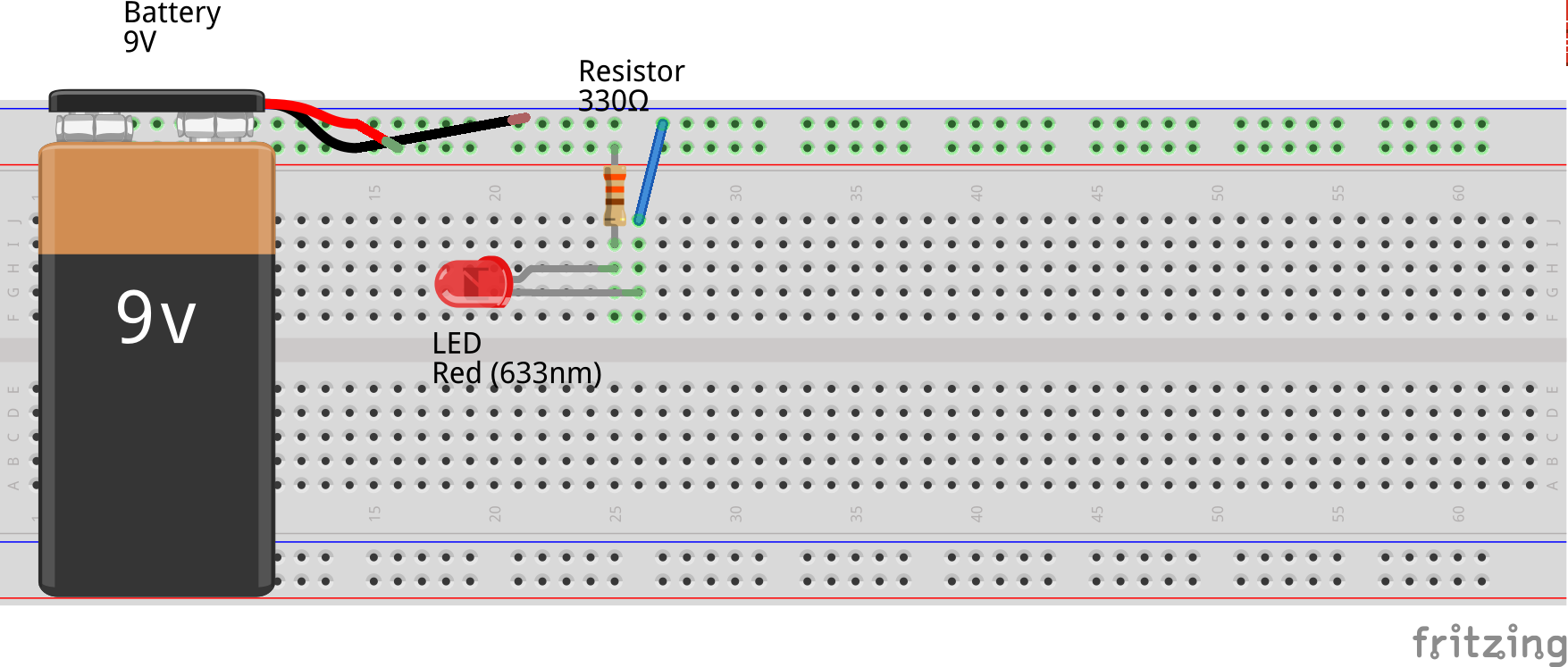
We will use an LED, a resistor, a jumper wire and a 9V battery with its cap and connectors.
It is a fairly simple circuit, easy to understand from a drawing. However, as we add more components and complexity to circuits, it will be harder to illustrate all connections and functions. This is why in electronics we use schematics.
A schematic is a diagram of the relationships of the electronic components in a circuit. In a schematic, you see the circuit components and how they are connected. This is the schematic of the circuit we are going to build: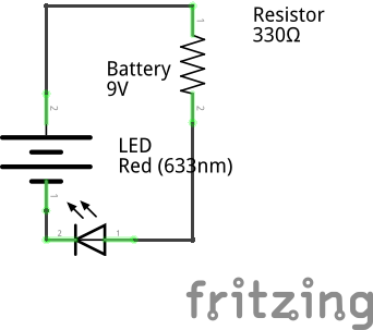
All common components have a symbol that is used to represent them in schematics. You can find more about them here and we will present each component's symbol as we go through the course.