Book
Meet the circuit
Meet the circuit
Completion requirements
View
The foundation of all electronics projects.
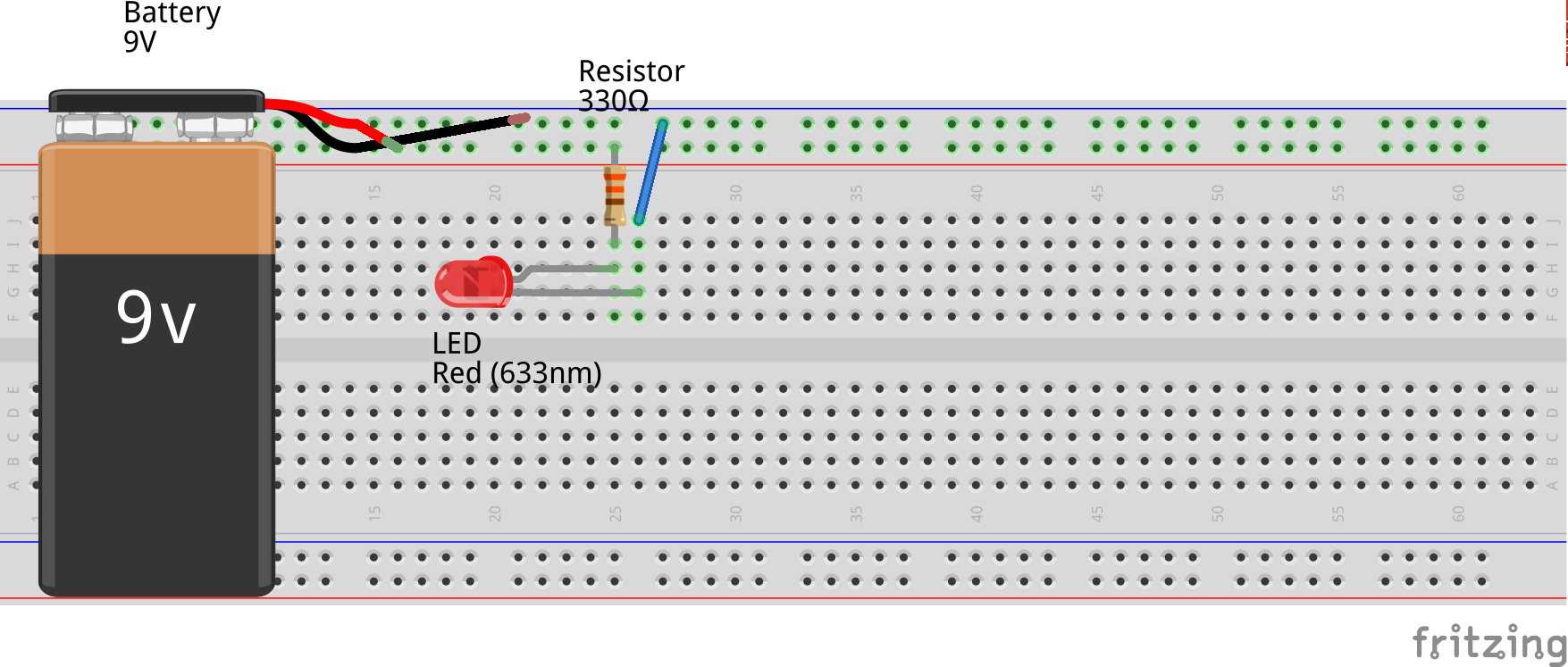
6. Build the circuit
You still may not understand how this circuit is going to work exactly. Worry not, as we will cover more about it in the next section! For now, gather the parts and follow along:
Pick the resistor
We will be using a 330 Ohm resistor. It is a resistor that has four bands with the colors orange, orange, brown, and gold.
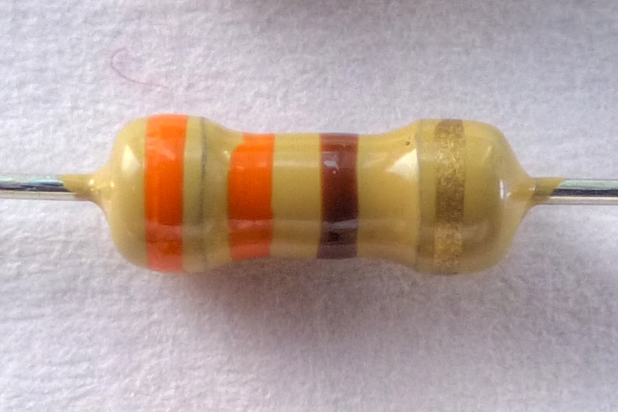
Resistors do not have polarity in a circuit, so it doesn’t matter what the orientation is. Each lead or leg is the same.
Add the LED
The anode (long lead) goes in the same row of tie points as the resistor. The cathode (short lead) goes into the next row.
Next we add a jumper wire to connect the LED cathode to the ground bus (-) of the breadboard.
Connect the power source
Next we connect the +/- poles of the battery to the +/- buses of the breadboard with the connectors. Typically, the black wire is used to connect the ground and the red for the positive end.
Let there be light!