Book
Input and output
Input and output
Completion requirements
View
Switches, speakers, LEDs, and flashing unicorns.
2. Add a button
The extra components we will need for this circuit are:
- One LED
- One 220Ω resistor (red, red, brown, gold)
- One 10kΩ resistor (brown, black, orange, gold)
- One pushbutton/tact switch
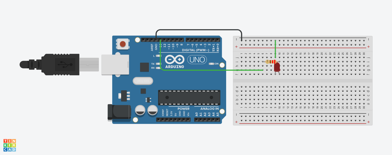
First we will connect the LED and its current limiting resistor to pin 13 like we did for the previous circuit:

In this example, it doesn't really matter whether the resistor connected in series to the LED is attached to the cathode or the anode side. So, we could instead build the following circuit with the same result:
If you would like to learn more about this, take a look at Kirchoff's circuit laws.
The schematic of the final circuit looks like this:
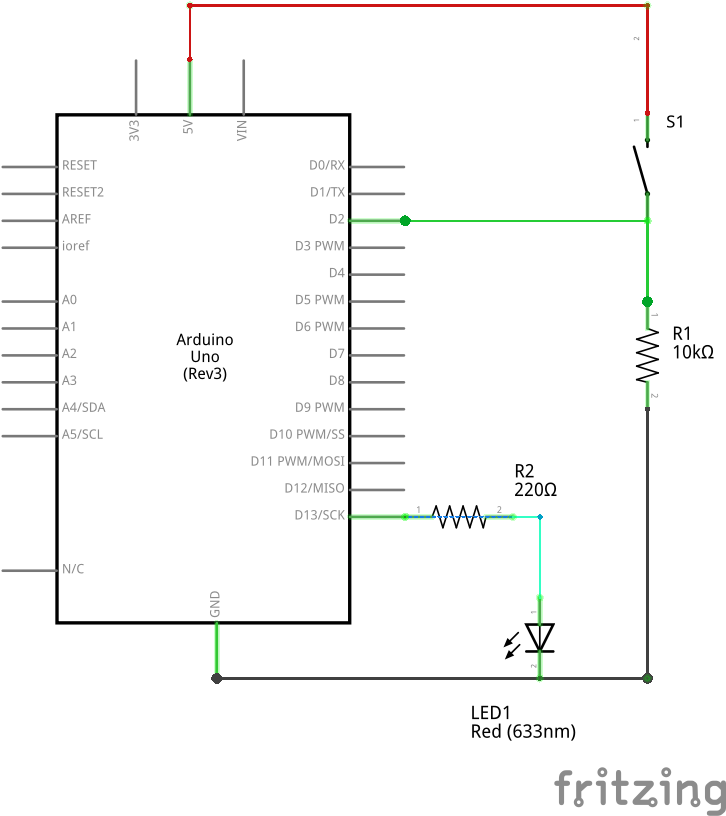
You may notice that S1 refers to the pushbutton. However, the pushbutton you have in your hands has 4 pins-ends instead of 2! This is because it actually contains 2 identical switches that open and close at the same time.
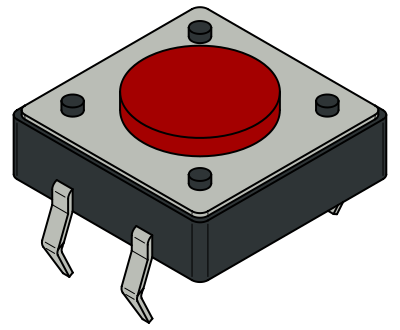
You may check which pin corresponds to which switch by using the multimeter. The main idea of the pushbutton is that when the button is pressed, the circuit is closed, and electricity can flow through it.
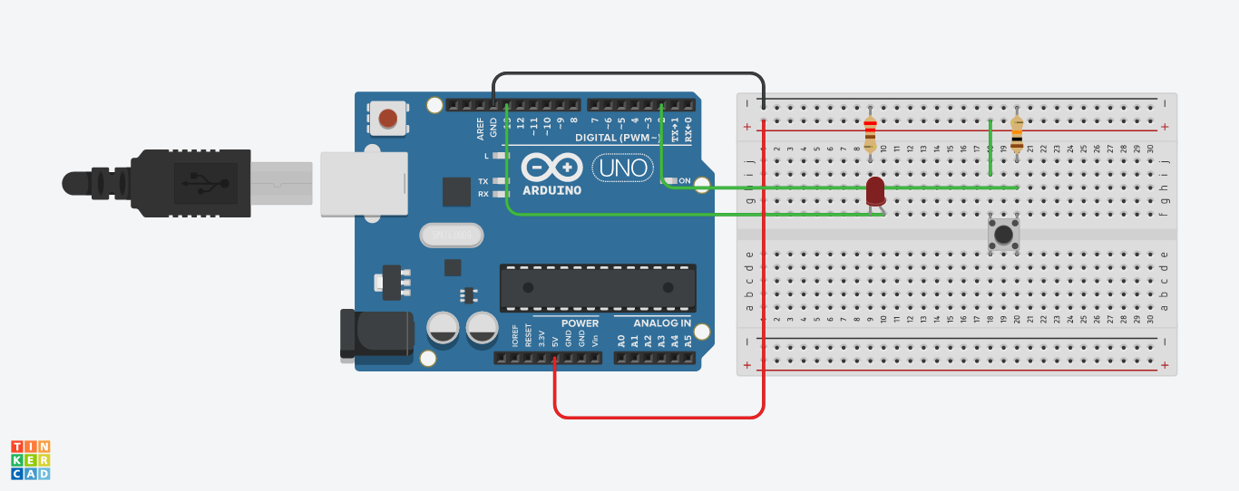
Next, we are going to add the pushbutton to the breadboard so that it straddles the dividing
line in the middle. The button will only fit this way in one orientation, the correct one.

We will now wire the pushbutton. First, we connect one of the button pins to the breadboard's 5V power
rail (+).
Next, we attach the 10 kΩ resistor; one side to the button and the other to the breadboard's ground rail (-).
Finally, we attach a jumper wire to pin 2 on the Arduino. This jumper will be attached to the 10 kΩ resistor that is attached to the ground rail.
After assembling the circuit, we may power the Arduino via the USB port and upload the sketch.
Launch the Arduino IDE, and then open the Button sketch by choosing File > Examples > 0.2 Digital > Button. Verify, upload, and then turn the LED on and off using the button!