From stick to strip
From stick to strip
Going big with addressable LEDs.
1. Powering strips
You can easily see by now that the example sketches used in the previous module are easily adapted for strips with more addressable LEDs.
However, the Arduino output pins do not provide enough current to drive a strip of LEDs. This is why we will be using a separate DC supply for the 1m strips we are going to connect to the Arduino UNO.
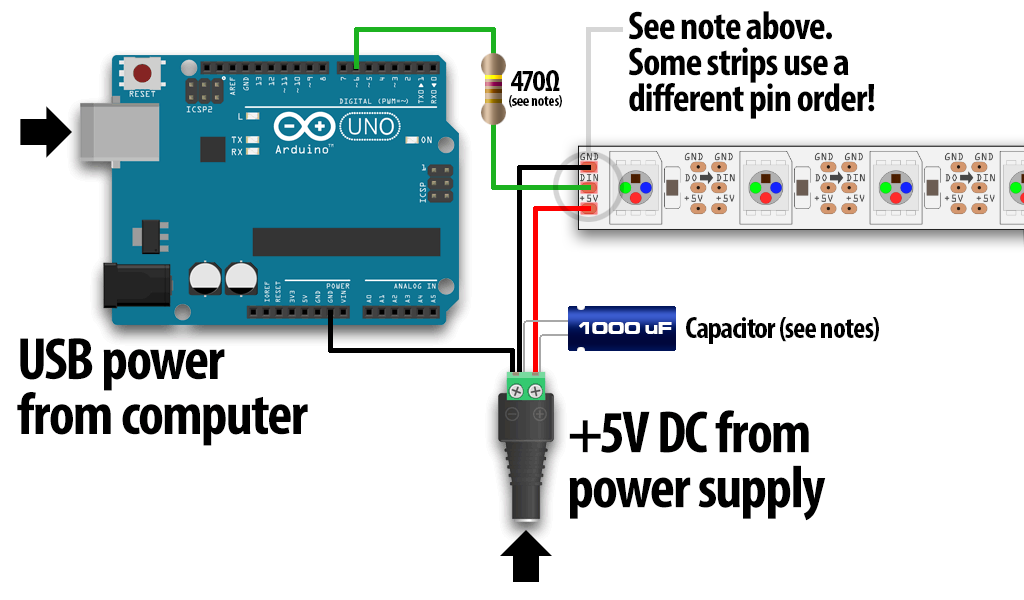
Identify the “input” end of your strip, pixel(s) or other
device; it will be labeled “DIN” or “DI” (data
input).
Then, connect
the +5V input on the strip to the + (positive) terminal on the power
supply (don’t connect to the Arduino), DIN to digital pin 6 on the
Arduino, and – (minus or GND) on the strip must connect to both the minus (–) terminal on the DC supply and a GND pin on the Arduino.